
Hub/Switch V2H124-24P Installation Guide
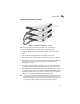

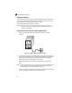
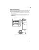
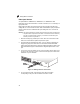

Making Network Connections
4-6
4
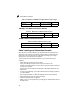
Table 4-4. Maximum 1000BASE-LH Gigabit Ethernet Cable Length
100 Mbps Fast Ethernet Collision Domain
Table 4-5. Maximum Fast Ethernet Cable Lengths
10 Mbps Ethernet Collision Domain
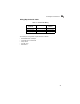
Table 4-6. Maximum Ethernet Cable Length
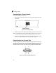
Cable Labeling and Connection Records
When planning a network installation, it is essential to label the opposing ends of
cables and to record where each cable is connected. Doing so will enable you to
easily locate inter-connected devices, isolate faults and change your topology
without need for unnecessary time consumption.
To best manage the physical implementations of your network, follow these
guidelines:
• Clearly label the opposing ends of each cable.
• Using your building’s floor plans, draw a map of the location of all
network-connected equipment. For each piece of equipment, identify the devices
to which it is connected.
• Note the length of each cable and the maximum cable length supported by the
switch ports.
• For ease of understanding, use a location-based key when assigning prefixes to
your cable labeling.
• Use sequential numbers for cables that originate from the same equipment.
• Differentiate between racks by naming accordingly.
• Label each separate piece of equipment.
• Display a copy of your equipment map, including keys to all abbreviations at each
equipment rack.
Fiber Size Fiber Bandwidth Maximum Cable Length Connector
9/125 micron
single-mode fiber
N/A 2 m - 70 km (7 ft - 43.5 miles) LC
Type Cable Type Max. Cable Length Connector
100BASE-TX Category 5 or better 100-ohm UTP or STP 100 m (328 ft) RJ-45
Cable Type Maximum Length Connector
Twisted Pair, Category 3 or better 100-ohm UTP 100 m (328 ft) RJ-45