Matrix V-Series V2H124-24P Fast Ethernet Switch Hardware Installation Guide P/N 9033976-01
ELECTRICAL HAZARD: Only qualified personnel should perform installation procedures. Notice ENTERASYS NETWORKS reserves the right to make changes in specifications and other information contained in this document and its web site without prior notice. The reader should in all cases consult ENTERASYS NETWORKS to determine whether any such changes have been made. The hardware, firmware, or software described in this document is subject to change without notice.
Notice Regulatory Compliance Information Federal Communications Commission (FCC) Notice This device complies with Part 15 of the FCC rules. Operation is subject to the following two conditions: (1) this device may not cause harmful interference, and (2) this device must accept any interference received, including interference that may cause undesired operation. NOTE: This equipment has been tested and found to comply with the limits for a class A digital device, pursuant to Part 15 of the FCC rules.
Notice VCCI Notice This is a class A product based on the standard of the Voluntary Control Council for Interference by Information Technology Equipment (VCCI). If this equipment is used in a domestic environment, radio disturbance may arise. When such trouble occurs, the user may be required to take corrective actions. Class A ITE Notice WARNING: This is a class A product. In a domestic environment this product may cause radio interference in which case the user may be required to take adequate measures.
Notice Safety Compliance Warning: Fiber Optic Port Safety CLASS I LASER DEVICE When using a fiber optic media expansion module, never look at the transmit laser while it is powered on. Also, never look directly at the fiber TX port and fiber cable ends when they are powered on. Avertissment: Ports pour fibres optiques - sécurité sur le plan optique DISPOSITIF LASER DE CLASSE I Ne regardez jamais le laser tant qu’il est sous tension.
Notice Please read the following safety information carefully before installing the switch: WARNING: Installation and removal of the unit must be carried out by qualified personnel only. • The unit must be connected to an earthed (grounded) outlet to comply with international safety standards. • Do not connect the unit to an A.C. outlet (power supply) without an earth (ground) connection.
Notice Power Cord Set Europe The supply plug must comply with CEE7/7 (“SCHUKO”). The mains cord must be or marked and be of type HO3VVF3GO.75 (minimum). IEC-320 receptacle. Veuillez lire à fond l'information de la sécurité suivante avant d'installer le Switch: AVERTISSEMENT: L’installation et la dépose de ce groupe doivent être confiés à un personnel qualifié.
Notice Cordon électrique - Il doit être agréé dans le pays d’utilisation Danemark: La prise mâle d’alimentation doit respecter la section 107-2 D1 de la norme DK2 1a ou DK2 5a. Suisse: La prise mâle d’alimentation doit respecter la norme SEV/ASE 1011. Europe La prise secteur doit être conforme aux normes CEE 7/7 (“SCHUKO”) LE cordon secteur doit porter la mention ou et doit être de type HO3VVF3GO.75 (minimum).
Notice Declaration of Conformity Application of Council Directive(s): Manufacturer’s Name: Manufacturer’s Address: European Representative Address: Conformance to Directive(s)/Product Standards: Equipment Type/Environment: 89/336/EEC 73/23/EEC Enterasys Networks, Inc. 50 Minuteman Road Andover, MA 01810 USA ENTERASYS NETWORKS, Ltd.
Notice Enterasys Networks, Inc. Firmware License Aggreement BEFORE OPENING OR UTILIZING THE ENCLOSED PRODUCT, CAREFULLY READ THIS LICENSE AGREEMENT. This document is an agreement (“Agreement”) between the end user (“You”) and Enterasys Networks, Inc.
Notice (ii) Incorporate the Program, in whole or in part, in any other product or create derivative works based on the Program, in whole or in part. (iii) Publish, disclose, copy, reproduce or transmit the Program, in whole or in part. (iv) Assign, sell, license, sublicense, rent, lease, encumber by way of security interest, pledge or otherwise transfer the Program, in whole or in part.
Notice 6. DISCLAIMER OF WARRANTY. EXCEPT FOR THOSE WARRANTIES EXPRESSLY PROVIDED TO YOU IN WRITING BY ENTERASYS, ENTERASYS DISCLAIMS ALL WARRANTIES, EITHER EXPRESS OR IMPLIED, INCLUDING BUT NOT LIMITED TO IMPLIED WARRANTIES OF MERCHANTABILITY, SATISFACTORY QUALITY, FITNESS FOR A PARTICULAR PURPOSE, TITLE AND NONINFRINGEMENT WITH RESPECT TO THE PROGRAM.
Notice 10. ENFORCEMENT. You acknowledge and agree that any breach of Sections 2, 4, or 9 of this Agreement by You may cause Enterasys irreparable damage for which recovery of money damages would be inadequate, and that Enterasys may be entitled to seek timely injunctive relief to protect Enterasys’ rights under this Agreement in addition to any and all remedies available at law. 11. ASSIGNMENT.
Contents Chapter 1: Introduction Overview Switch Architecture Power-over-Ethernet Capability Network Management Options Description of Hardware 10/100BASE-T Ports 1000BASE-T/SFP Ports Port and System Status LEDs Stack Master Button Mode PoE/Link Button Optional Stacking Transceiver Power Supply Receptacle Features and Benefits Connectivity Performance Management Chapter 2: Network Planning Introduction to Switching Application Examples Collapsed Backbone Network Aggregation Plan Remote Connections with Fibe
Contents Installing a Stacking Transceiver 3-6 Connecting Switches in a Stack 3-7 Connecting to a Power Source 3-8 Connecting to the Console Port 3-8 Wiring Map for Serial Cable 3-9 Chapter 4: Making Network Connections 4-1 Connecting Network Devices 4-1 Twisted-Pair Devices 4-1 Power-over-Ethernet Connections 4-1 Cabling Guidelines 4-2 Connecting to PCs, Servers, Hubs and Switches 4-2 Network Wiring Connections 4-3 Fiber Optic Devices 4-4 Connectivity Rules 4-5 1000BASE-T Cable Requirements 4-5 1000 Mbps G
Contents Glossary Index xv
Tables Table 1-1. Table 1-2. Table 3-1. Table 4-1. Table 4-2. Table 4-3. Table 4-4. Table 4-5. Table 4-6. Table A-1. Table B-1. Table B-2.
Figures Figure 1-1. Figure 1-2. Figure 1-3. Figure 1-4. Figure 1-5. Figure 1-6. Figure 1-7. Figure 2-1. Figure 2-2. Figure 2-3. Figure 2-4. Figure 3-1. Figure 3-2. Figure 3-3. Figure 3-4. Figure 3-5. Figure 3-6. Figure 3-7. Figure 3-8. Figure 3-9. Figure 4-1. Figure 4-2. Figure 4-3. Figure B-1. Figure B-2. Figure B-3.
Figures xviii
Chapter 1: Introduction Overview The Matrix V-Series V2H124-24P switch contains 24 10BASE-T/100BASE-TX RJ-45 ports and two combination ports—10/100/1000BASE-T ports that operate in combination with Small Form Factor Pluggable (SFP) transceiver slots. An optional SFP stacking transceiver is available for connecting up to eight units to a 1 Gbps stack backplane. All the 10BASE-T/100BASE-TX ports on this switch support IEEE 802.3af draft standard (802.3af) Power-over-Ethernet capabilities.
1 Introduction This switch includes two Gigabit combination ports with RJ-45 connectors and associated SFP slots. The optional SFP stacking transceiver enables up to eight units to be connected together through a 1 Gbps stack backplane. The switch stack can be managed from a master unit using a single IP address. Power-over-Ethernet Capability The switch’s 24 10/100 Mbps ports support the IEEE 802.
1 Description of Hardware Description of Hardware 10/100BASE-T Ports The PoE switch base unit contains 24 10BASE-T/100BASE-TX RJ-45 ports. All ports support automatic MDI/MDI-X operation, so you can use straight-through cables for all network connections to PCs or servers, or to other switches or hubs. (See "10/100BASE-TX Pin Assignments" on page B-1.
1 Introduction The port status LEDs have two display modes: Link and PoE. The Link mode displays the link status and network activity on each port. The PoE mode displays the PoE power status on each port. Use the Mode Link/PoE button (see "Mode PoE/ Link Button" on page 1-6) on the front panel to toggle between the two display modes. The current mode is indicated by the Link/Act and PoE system LEDs. Table 1-1.
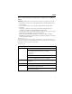
1 Description of Hardware Table 1-2. System Status LEDs LED Condition PWR On Green Unit’s internal power supply is operating normally. Off Unit has no power connected. Diag Status On Green System diagnostic test successfully completed . Flashing Green System diagnostic test is in progress. On Amber System diagnostic test has detected a fault. Flashing Amber Cannot receive packet from stacking port. Alternate Green/Amber Fan has failed or the unit has over-heated.
1 Introduction Stack Master Button The unit also includes a Stack Master button that is shown in the following diagram. Stack Master Button Figure 1-4. Stack Master Button The Stack Master button enables one switch in the stack to be selected as the master. Mode PoE/Link Button The Mode PoE/Link button is located on the front panel. Mode Select Button Link/Act PWR PoE Diag 25 26 Stacking Mode PoE/Link Figure 1-5.
Description of Hardware 1 Optional Stacking Transceiver TX RX Figure 1-6. Optional Stacking Transceiver The stacking transceiver provides two 1 Gbps ports via USB Type-A connectors. The upper port is a transmit port and the lower one is a receive port. The transceiver allows up to eight switches to be linked together using stacking cables. (One stacking cable is included with each optional stacking transceiver.
1 Introduction Features and Benefits Connectivity • 24 dual-speed ports for easy Fast Ethernet integration and for protection of your investment in legacy LAN equipment • All 10/100 RJ-45 ports support IEEE 802.
Chapter 2: Network Planning Introduction to Switching A network switch allows simultaneous transmission of multiple packets via non-crossbar switching. This means that it can partition a network more efficiently than bridges or routers. The switch has, therefore, been recognized as one of the most important building blocks for today’s networking technology.
2 Network Planning Application Examples The Matrix V-Series V2H124-24P switch is not only designed to segment your network, but also to provide a wide range of options in setting up network connections. Some typical applications are described below. Collapsed Backbone The Matrix V-Series V2H124-24P switch is an excellent choice for mixed Ethernet and Fast Ethernet installations in which significant growth is expected in the near future.
2 Application Examples Network Aggregation Plan With 24 parallel bridging ports (i.e., 24 distinct collision domains), the Matrix V-Series PoE switch can collapse a complex network down into a single efficient bridged node, increasing overall bandwidth and throughput. When up to eight switch units are stacked together, they form a single “virtual” switch containing up to 200 ports. The whole stack can be managed through the Master unit using a single IP address.
2 Network Planning Remote Connections with Fiber Cable Fiber optic technology allows for longer cabling than any other media type. Using a 1000BASE-SX multimode fiber (MMF) SFP transceiver, you can run a link up to 550 m. A 1000BASE-LX single-mode fiber (SMF) link can run up to 5 km. A 1000BASE-LH single-mode fiber (SMF) link can run up to 70 km. This allows the switch to serve as a collapsed backbone, providing direct connectivity for a widespread LAN.
2 Application Examples Making VLAN Connections This switch supports VLANs which can be used to organize any group of network nodes into separate broadcast domains. VLANs confine broadcast traffic to the originating group, and can eliminate broadcast storms in large networks. This provides a more secure and cleaner network environment. VLANs can be based on untagged port groups, or traffic can be explicitly tagged to identify the VLAN group to which it belongs.
2 Network Planning Application Notes 1. Full-duplex operation only applies to point-to-point access (such as when a switch is attached to a workstation, server or another switch). When the switch is connected to a hub, both devices must operate in half-duplex mode. 2. Avoid using flow control on a port connected to a hub unless it is actually required to solve a problem. Otherwise back pressure jamming signals may degrade overall performance for the segment attached to the hub. 3.
Chapter 3: Installing the Switch Selecting a Site Matrix V-Series V2H124-24P units can be mounted in a standard 19-inch equipment rack or on a flat surface. Be sure to follow the guidelines below when choosing a location. • The site should: - be at the center of all the devices you want to link and near a power outlet.
3 Installing the Switch RJ-45 Connector Figure 3-1. RJ-45 Connections Equipment Checklist After unpacking this switch, check the contents to be that sure you have received all the components. Then, before beginning the installation, be sure that you have all other necessary installation equipment.
Mounting 3 Optional Rack-Mounting Equipment If you plan to rack-mount the switch, be sure to have the following equipment available: • Four mounting screws for each device you plan to install in a rack—these are not included • A screwdriver (Phillips or flathead, depending on the type of screws used) Mounting This switch can be mounted in a standard 19-inch equipment rack or on a desktop or shelf. Mounting instructions for each type of site follow.
3 Installing the Switch 2. Mount the device in the rack, using four rack-mounting screws (not provided). 25 26 Link/A ct PW R PoE Diag V2H 25 26 124 -24 Stac king P Mo PoE/de Link Figure 3-3. Installing the Switch in a Rack 3. If installing a single switch only, turn to “Connecting to a Power Source” at the end of this chapter. 4. If installing multiple switches, mount them in the rack, one below the other, in any order.
3 Installing an SFP Transceiver 2. Set the device on a flat surface near an AC power source, making sure there are at least two inches of space on all sides for proper air flow. 3. If installing a single switch only, go to “Connecting to a Power Source” at the end of this chapter. 4. If installing multiple switches, attach four adhesive feet to each one. Place each device squarely on top of the one below, in any order.
3 Installing the Switch Stacking Switches The switch supports stacking up to eight units through an optional SFP stacking transceiver. The stacking transceiver must be installed in the port 25 slot. Each stacking transceiver has two connectors, Tx and Rx, for attaching stacking cables. Figure 3-7 shows how stacking cables are connected between switches in a stack. Note: The stacking transceiver must only be installed in the port 25 SFP slot.
3 Stacking Switches Connecting Switches in a Stack 13 13 14 15 Stack Master 16 17 18 19 20 21 22 23 24 23 14 25 26 24 Link/A ct PWR x PoE T V2H Diag 124 25 x R 26 Stack -24 P ing Mode PoE/L ink 13 13 14 15 Slave 16 17 18 19 20 21 22 23 24 23 14 25 26 Link/A ct PWR x T PoE V2H 124 Diag -24 P 25 x R 26 Stack ing Mode PoE/L ink 13 13 14 15 Slave 16 17 18 19 20 21 22 23 24 23 14 25 26 24 Link/A ct PWR x T PoE V2H Diag 124 -24 P 25 x
3 Installing the Switch Connecting to a Power Source To connect a switch to a power source: 1. Insert the power cable plug directly into the AC receptacle located at the back of the switch. 100-240V~ 50-60Hz 7.5A Power Socket Figure 3-8. Power Receptacle 2. Plug the other end of the cable into a grounded, 3-pin socket, AC power source. Note: For international use, you may need to change the AC line cord. You must use a line cord set that has been approved for the receptacle type in your country. 3.
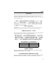
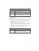
Connecting to the Console Port 3 Wiring Map for Serial Cable Table 3-1. Serial Cable Wiring Switch’s 9-Pin Serial Port Null Modem PC’s 9-Pin DTE Port 2 RXD (receive data) <---------------------------- 3 TXD (transmit data) -----------------------------> 2 RXD (receive data) 5 SGND (signal ground) ------------------------------ 3 TXD (transmit data) 5 SGND (signal ground) No other pins are used.
3 Installing the Switch 3-10
Chapter 4: Making Network Connections Connecting Network Devices The Matix V-Series V2H124-24P switch is designed to be connected to 10 or 100 Mbps network cards in PCs and servers, as well as to other switches and hubs. It may also be connected to remote devices using the optional 1000BASE-SFP transceivers. If 802.3af-compliant PoE devices are connected to the switch’s 10/100 Mbps ports, the switch automatically supplies the required power.
4 Making Network Connections Cabling Guidelines The RJ-45 ports on the switch support automatic MDI/MDI-X pinout configuration, so you can use standard straight-through twisted-pair cables to connect to any other network device (PCs, servers, switches, routers, or hubs). See Appendix B for further information on cabling. Caution: Do not plug a normal phone jack connector into an RJ-45 port. This will damage the switch. Use only twisted-pair cables with RJ-45 connectors that conform to FCC standards.
Twisted-Pair Devices 4 Network Wiring Connections Today, the punch-down block is an integral part of many newer equipment racks. It is actually part of the patch panel. Instructions for making connections in the wiring closet with this type of equipment follow. 1. Attach one end of a patch cable to an available port on the switch, and the other end to the patch panel. 2.
4 Making Network Connections Fiber Optic Devices An optional slide-in 1000BASE-SX, 1000BASE-LX, or 1000BASE-LH SFP transceiver may be used for backbone or remote connections, or for connecting to a high-speed server. Each single-mode fiber optic port requires 9/125 micron single-mode fiber optic cabling with an LC connector at both ends. Each multimode fiber optic port requires 50/125 or 62.5/125 micron multimode fiber optic cabling with an LC connector at both ends.
Connectivity Rules 4 Connectivity Rules When adding hubs (repeaters) to your network, please follow the connectivity rules listed in the manuals for these products. However, note that because switches break up the path for connected devices into separate collision domains, you should not include the switch or connected cabling in your calculations for cascade length involving other devices.
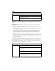
4 Making Network Connections Table 4-4. Maximum 1000BASE-LH Gigabit Ethernet Cable Length Fiber Size Fiber Bandwidth Maximum Cable Length 9/125 micron single-mode fiber N/A 2 m - 70 km (7 ft - 43.5 miles) LC Connector 100 Mbps Fast Ethernet Collision Domain Table 4-5. Maximum Fast Ethernet Cable Lengths Type Cable Type Max. Cable Length 100BASE-TX Category 5 or better 100-ohm UTP or STP 100 m (328 ft) Connector RJ-45 10 Mbps Ethernet Collision Domain Table 4-6.
Appendix A: Troubleshooting Diagnosing Switch Indicators Table A-1. Troubleshooting Chart Symptom Action PWR LED is Off • Internal power supply may be disconnected. Check connections between the switch, the power cord and the wall outlet. Diag LED is Amber • The system has detected a fault. Power cycle the switch to try and clear the condition. • If the condition does not clear, contact your dealer for assistance. Diag LED is Flashing Amber • Check that all stacking cables are properly connected.
A Troubleshooting Installation Verify that all system components have been properly installed. If one or more components appear to be malfunctioning (such as the power cord or network cabling), test them in an alternate environment where you are sure that all the other components are functioning properly. In-Band Access You can access the management agent in the switch from anywhere within the attached network using Telnet, a web browser, or other network management software tools.
Appendix B: Cables Twisted-Pair Cable and Pin Assignments Caution: DO NOT plug a normal phone jack connector into any RJ-45 port. Use only twisted-pair cables with RJ-45 connectors that conform with FCC standards. For 10/100BASE-TX connections, the twisted-pair cable must have two pairs of wires. For 1000BASE-T connections the twisted-pair cable must have four pairs of wires. Each wire pair is identified by two different colors. For example, one wire might be green and the other, green with white stripes.
B Cables Table B-1.
Twisted-Pair Cable and Pin Assignments B White/Orange Stripe Orange End A White/Green Stripe 1 2 3 4 5 6 7 8 Blue White/Blue Stripe Green White/Brown Stripe 1 2 3 4 5 6 7 8 End B Brown Stripe Figure B-3. Crossover Wiring 1000BASE-T Pin Assignments All 1000BASE-T ports support automatic MDI/MDI-X operation, so you can use straight-through cables for all network connections to PCs or servers, or to other switches or hubs. The table below shows the 1000BASE-T MDI and MDI-X port pinouts.
B Cables Cable Testing for Existing Category 5 Cable Installed Category 5 cabling must pass tests for Attenuation, Near-End Crosstalk (NEXT), and Far-End Crosstalk (FEXT). This cable testing information is specified in the ANSI/TIA/EIA-TSB-67 standard. Cables must also pass test parameters for Return Loss and Equal-Level Far-End Crosstalk (ELFEXT). These tests are specified in the ANSI/TIA/EIA-TSB-95 Bulletin, “The Additional Transmission Performance Guidelines for 100 Ohm 4-Pair Category 5 Cabling.
Appendix C: Specifications Physical Characteristics Ports 24 10/100BASE-TX, with auto-negotiation 2 1000BASE-T/SFP combination ports Network Interface Ports 1-24: RJ-45 connector, auto MDI/X 10BASE-T: RJ-45 (100-ohm, UTP cable; Categories 3 or better) 100BASE-TX: RJ-45 (100-ohm, UTP cable; Category 5 or better) Ports 25, 26: RJ-45 connector, auto MDI/X 1000BASE-T: RJ-45 (100-ohm, UTP cable; Category 5, 5e, or 6) Buffer Architecture 8 Mbytes Aggregate Bandwidth 8.
C Specifications Power-over-Ethernet Input voltage: - 48 V DC Maximum output power per port: 15.4 W Output Voltage: 44 - 57 V DC Maximum output current per port: 350 mA DC Power Supply Internal, auto-ranging transformer: 100 to 240 VAC, 47 to 63 Hz Power Consumption 48 Watts (Switching system) 370 Watts (Power-over-Ethernet) Maximum Current 8 A @ 110 VAC 4 A @ 240 VAC Switch Features Forwarding Mode Store-and-forward Throughput Connections between front panel ports are line rate.
Standards C Standards IEEE 802.3 Ethernet IEEE 802.3u Fast Ethernet IEEE 802.3af Power-over-Ethernet IEEE 802.3p priority tags IEEE 802.3ac VLAN tagging IEEE 802.1D Bridging IEEE 802.1x Port access control IEEE 802.3x full-duplex flow control ISO/IEC 8802-3 Carrier sense multiple access with collision detection (CSMA/CD) Compliances Safety UL 60950 CSA C22.2 No. 60950 73/23/EEC EN 60950 IEC 60950 EN 60825 CFR 1040.10 Electromagnetic Compatibility (EMC) 47 CFR Parts 2 and 15 CSA C108.
C C-4 Specifications
Glossary 10BASE-T IEEE 802.3 specification for 10 Mbps Ethernet over two pairs of Category 3, 4, or 5 UTP cable. 100BASE-TX IEEE 802.3u specification for 100 Mbps Ethernet over two pairs of Category 5 UTP cable. 1000BASE-LH Long haul Gigabit Ethernet over two strands of 9/125 micron core fiber cable. 1000BASE-T IEEE 802.3ab specification for Gigabit Ethernet over 100-ohm Category 5, 5e or 6 twisted-pair cable (using all four wire pairs).
Glossary Ethernet A network communication system developed and standardized by DEC, Intel, and Xerox, using baseband transmission, CSMA/CD access, logical bus topology, and coaxial cable. The successor IEEE 802.3 standard provides for integration into the OSI model and extends the physical layer and media with repeaters and implementations that operate on fiber, thin coax and twisted-pair cable. Fast Ethernet A 100 Mbps network communication system based on Ethernet and the CSMA/CD access method.
Glossary LAN Segment Separate LAN or collision domain. LED Light emitting diode used for monitoring a device or network condition. Local Area Network (LAN) A group of interconnected computer and support devices. Modal Bandwidth Bandwidth for multimode fiber is referred to as modal bandwidth because it varies with the modal field (or core diameter) of the fiber. Modal bandwidth is specified in units of MHz per km, which indicates the amount of bandwidth supported by the fiber for a one km distance.
Glossary Virtual LAN (VLAN) A Virtual LAN is a collection of network nodes that share the same collision domain regardless of their physical location or connection point in the network. A VLAN serves as a logical workgroup with no physical barriers, allowing users to share information and resources as though located on the same LAN.
Index Numerics D 10 Mbps connectivity rules 4-6 100 Mbps connectivity rules 4-6 1000 Mbps connectivity rules 4-5 100BASE cable lengths 4-6 100BASE-TX ports 1-3 10BASE cable lengths 4-6 10BASE-T ports 1-3 desktop mounting 3-4 device connections 4-1 A F adhesive feet, attaching 3-4 air flow requirements 3-1 applications central wiring closet 2-3 collapsed backbone 2-2 remote connections with fiber 2-4 VLAN connections 2-5 E electrical interference, avoiding 3-1 equipment checklist 3-2 Ethernet connecti
Index L laser safety 4-4 LED indicators Diag 1-5 Power 1-5 problems A-1 Stack 1-5 location requirements 3-1 RJ-45 port 1-3 connections 4-1 pinouts B-3 RMON 1-2 RS-232 port 1-2 rubber foot pads, attaching 3-4 S out-of-band management 1-2 screws for rack mounting 3-3 serial cable 1-2 port 1-2 single-mode fiber optic cables 4-4 site selelction 3-1 SNMP agent 1-2 specifications compliances C-2 environmental C-1 physical C-1 power C-2 standards compliance C-2 IEEE C-3 status LEDs 1-3 surge suppressor, using
ES3526-PoE-60 P/N 150200039300A E042004-R01 E072000-R04