Aurorean™ Virtual Network RiverMaster Administrator’s Guide Version 3.
©2001 Enterasys Networks. All rights reserved. This publication contains information that is the property of Enterasys Networks. No part of this publication may be copied, photocopied, reproduced, translated, or reduced to any electronic medium or machine readable form without prior written consent of Enterasys Networks. Information in this publication is subject to change without notice.
Table of Contents About This Guide Contents of the Guide ........................................................................................................... ix Conventions Used in this Guide.......................................................................................... xi Related Documents................................................................................................................ xi Chapter 1 – Installing RiverMaster Software System Requirements .....................
Table of Contents Chapter 3 – Configuring an ANG-3000/7000 Before You Begin ................................................................................................................... 26 Allocating IP/IPX Addresses to Remote Clients....................................................... 27 Virtual Subnets for Site-to-Site and Remote Access Tunnel Servers.............. 30 Intelligent Client Routing .............................................................................................
Table of Contents Chapter 4 – Setting Up Aurorean Services Before You Begin ....................................................................................................................75 Authorization Plug-in Options .....................................................................................76 RADIUS Authentication Servers .......................................................................... 76 Plug-in Planning .........................................................................
Table of Contents Adding POPs for Corporate ISPs.......................................................................................114 Chapter 6 – Managing Users & Groups Before You Begin ................................................................................................................. 120 Group Policies .............................................................................................................. 121 Aurorean Client Installation Kits.....................................
Table of Contents Chapter 8 – Generating Reports Report Contents....................................................................................................................177 Server Anomaly Report ...............................................................................................177 Network Gateway Report............................................................................................179 Client Anomaly Report ..................................................................
Table of Contents Configuring Routing Interfaces ........................................................................................ 234 Configuring RIP for the Interface .............................................................................. 236 Configuring OSPF on an Interface ............................................................................ 238 Creating Static Routes .................................................................................................
About This Guide This guide describes how to use Version 3.1 of the RiverMaster management application to set up and monitor Aurorean Virtual Network systems. While written primarily to describe how to configure a Aurorean Virtual Network solution for the first time, this guide also addresses how to track usage and troubleshoot end-to-end VPN connectivity problems. The guide is designed for network administrators who are responsible for installing and managing local and wide area networking equipment.
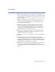
About This Guide H Chapter 5, Controlling Remote User Dialing & Access describes how to define Aurorean Network Gateway destinations, select ISPs from the TollSaver database, configure POP packages and add corporate dialup phone numbers. H Chapter 6, Managing Users & Groups addresses how to create a user database on a Aurorean Policy Server, assign policies that govern user access to the network, and prepare a customized Aurorean Client Software installation kit.
About This Guide Conventions Used in this Guide The following conventions are used in this guide: NOTE Notes supply additional helpful information, point you to where you can find more information, or emphasize critical issues you should consider when performing an action. CAUTION Cautions contain directions that can prevent you from damaging the product or losing data. WARNING Warnings provide directions that you must follow to avoid harming yourself.
About This Guide later), you can view these manuals on-line or print additional copies. Acrobat Reader can be downloaded from the Adobe web site (www.adobe.com).
1 Installing RiverMaster Software This chapter provides the system requirements and step-by-step instructions for installing RiverMaster software on your computer. If you have not already done so, Enterasys Networks recommends that you mount and connect your Aurorean Policy Server and Aurorean Network Gateway before performing these steps. Refer to the Aurorean Installation & Service Guide supplied with each server for detailed installation instructions.
Chapter 1 Installing RiverMaster Software Installing the Application Software Requirements The following operating systems, applications, and protocols should be installed and configured before you install RiverMaster: H Windows NT 4.
Chapter 1 Installing RiverMaster Software Installing the Application 3 If a warning message appears stating that Microsoft ODBC is not present on your computer, click OK to install Microsoft ODBC. If this message does not appear, continue with the next step. The Microsoft ODBC text driver must be installed on your computer in order for RiverMaster to generate reports. RiverMaster Setup automatically launches the Microsoft ODBC install program; follow the instructions provided on the screen.
Chapter 1 Installing RiverMaster Software Installing the Application 10 When the Setup Complete window appears, do one of the following: – To view the README file immediately, leave the check box checked and click Finish. – To wait until later to view the README file, remove the check from the check box and click Finish. 11 At the second Setup Complete window, choose Yes to restart your computer and click Finish.
Chapter 1 Installing RiverMaster Software Installing the Application To start RiverMaster, perform the following steps: 1 On the main Windows NT/2000 desktop, double-click the RiverMaster icon. Alternatively, you can click the Start button, point to Programs, point to Indus River Networks, and then click RiverMaster. In the RiverMaster program group, click RiverMaster to launch the application. After a few seconds, the Identify Your Aurorean Environment window appears as shown in Figure 1.
Installing the Application 3 Chapter 1 Installing RiverMaster Software Do one of the following: – If you are configuring only one Aurorean Policy Server, enter the IP address assigned to it in the Primary fields and click OK. The RiverMaster Login window will appear as shown in Figure 3 with the Aurorean VN Name, APS name and IP address displayed as you specified earlier. Skip to Step 5.
Chapter 1 Installing RiverMaster Software 5 Installing the Application Type the default user name (netadmin) and password (netadmin) and click OK. For example, the primary APS name and its IP address is displayed in the RiverMaster Login window in Figure 3. When the RiverMaster application starts, the main interface appears as shown in Figure 4.
Chapter 1 Installing RiverMaster Software Installing the Application Using the Delivery service running on all Aurorean components, RiverMaster establishes a Delivery session with each server. The Aurorean Policy Server reports service status, memory/hard disk usage, and a summary of alarms, alerts, and problem notification messages. The Aurorean Network Gateway reports an aggregated total of bytes sent and received over all tunnels, as well as memory/hard disk usage.
Chapter 1 Installing RiverMaster Software Removing RiverMaster Files Removing RiverMaster Files RiverMaster can be uninstalled from your computer using the standard Add/Remove Programs tool provided with Windows. After RiverMaster files are removed from your computer, you should restart the computer to clean up any files that were in use during the uninstall.
Removing RiverMaster Files Chapter 1 Installing RiverMaster Software 10 Locate the RiverMaster program folder. The default location for this folder is C:\Program Files\ Indus River Networks. 11 Delete the RiverMaster folder. 12 Restart your computer.
2 Getting Started with RiverMaster This chapter introduces the essential functions of RiverMaster, describes Aurorean Virtual Network system status information displayed on the main interface, and summarizes the steps required to use RiverMaster to configure your Aurorean Virtual Network for the first time.
Chapter 2 Getting Started with RiverMaster RiverMaster Overview Aurorean Policy Server • Backup configuration files • Log files • Updated configurations • Requests for logs ns tio ra gu s nfi ce co rvi nt f se re ur s o • C tatu orts • S Rep • es ng t ha rts ien p c po Cl ou re n ds gr for rea an r & ts uro m se ues A com • U Req stom uild • Cu i t b • k •N co otifi nfi ca gu tio ra n o ti o f nc ha ng es •T un ne ls tat ist i cs Aurorean Network Gateway RiverMaster PC Figure 5 Aurorean Virtual
Chapter 2 Getting Started with RiverMaster Logging into RiverMaster H Organize users with groups and assign each group policies that govern the features available in Aurorean Client Software. H Create customized Aurorean Client Software installation kits to distribute to your remote users that contains the Aurorean Client Software application, POP packages, group policies, and destination IP addresses.
Chapter 2 Getting Started with RiverMaster Logging into RiverMaster NOTE To prevent unauthorized RiverMaster access, Enterasys Networks recommends that you immediately create a new administrator login account in the IRAdmin group and delete the default login account. Refer to Chapter 6 for more on adding and deleting user accounts. If you have configured a connection to a second Aurorean Policy Server, the Select APS window appears as shown in Figure 7.
Chapter 2 Getting Started with RiverMaster Checking Server Status Checking Server Status RiverMaster’s main interface is designed to quickly show the Aurorean Virtual Network’s “health” when you start the application.
Chapter 2 Getting Started with RiverMaster Checking Server Status Indicates current alarms, alerts, and informational messages that appear in the System Activity window (refer to Chapter 7 for more information) Click here to view more details about logged in users Total number of remote users authenticated and connected to the corporate network via the Aurorean Network Gateway Figure 8 Aurorean Network Gateway Status Information Aurorean Network Gateway Statistics Figure 9 shows the statistics informa
Chapter 2 Getting Started with RiverMaster Checking Server Status Aggregated number of bytes received and sent over all tunnels processed by the Aurorean Network Gateway Click here to view detailed statistics for individual tunnels (refer to Chapter 7 for details) Memory usage Hard disk usage Figure 9 Aurorean Network Gateway Statistics The memory and hard disk usage meters show how much system resources are being consumed supporting tunnel connections.
Chapter 2 Getting Started with RiverMaster Checking Server Status Status of services running or stopped on the Aurorean Policy Server Memory usage Hard disk usage Figure 10 Aurorean Network Gateway Statistics Table 1 Aurorean Policy Server Services Service Function If Stopped... Overlord Monitors the condition of all other Aurorean services and restarts a service if it fails to initialize properly or ceases to operate at any point. Overlord may also force a total server reboot if necessary.
Chapter 2 Getting Started with RiverMaster Checking Server Status Table 1 Aurorean Policy Server Services Service Function If Stopped... Notification Reports alarm, alert, and problem notification messages using E-mail. The Aurorean Policy Server and Network Gateway can operate normally but E-mail messages are no longer sent when alarms/alerts/problems occur. FTP Provides the mechanism for transferring files between Aurorean Virtual Network servers and RiverMaster.
Chapter 2 Getting Started with RiverMaster Checking Server Status Table 1 Aurorean Policy Server Services Service Function If Stopped... Log Maintains a running record of system events and messages received by each Aurorean Virtual Network component. The RiverMaster application displays these logs and extracts information from them to produce daily reports. The Aurorean Policy Server will accept configuration changes and the Aurorean Network Gateway will accept tunnel connection attempts.
Chapter 2 Getting Started with RiverMaster Setting Up a Aurorean Virtual Network the First Time Setting Up a Aurorean Virtual Network the First Time When you start RiverMaster for the first time, you need to perform several basic configuration steps to put your Aurorean Virtual Network into operation. These basic steps are outlined below, with references to the detailed instructions provided throughout this manual.
Setting Up a Aurorean Virtual Network the First Time Chapter 2 Getting Started with RiverMaster 6 Create mailing lists so that the Aurorean Policy Server sends you E-mail when alarm, alert, or notification messages are generated (optional). E-mail messages are generated by the Notification service as described in Chapter 4. 7 Reboot the Aurorean Network Gateway to put the networking changes into effect.
Chapter 2 Getting Started with RiverMaster Setting Up a Aurorean Virtual Network the First Time Once remote users begin tunneling into the corporate network using Aurorean Client Software software, you can view this activity using the Tunnel Statistics window described in Chapter 7. You can also produce detailed daily usage reports as described in Chapter 8. Authentication requests and other user activity messages are also displayed in the System Activity window described in Chapter 7.
3 Configuring an ANG-3000/7000 This chapter describes how to configure network settings for your local Aurorean Network Gateway (ANG-3000/7000). Local ANGs have an accompanying Aurorean Policy Server and are configured using RiverMaster. Remote ANGs are stand-alone systems configured by using the Web-based Aurorean Policy Manager utility. The ANG-1000 is configured using its Webbased configuration utility only.
Chapter 3 Configuring an ANG-3000/7000 Before You Begin These functions are grouped on the Configuration pullout as shown in Figure 11.
Chapter 3 Configuring an ANG-3000/7000 Before You Begin Allocating IP/IPX Addresses to Remote Clients When remote clients tunnel into the corporate network, they must be able to access devices on the network just as if they were locally connected. To serve this need, the ANG acts as a router, forwarding packets between devices on the corporate network and remote clients. When remote clients tunnel into the ANG, they must be allocated IP addresses accessible to or on the local network.
Chapter 3 Configuring an ANG-3000/7000 Before You Begin Virtual subnets can use both legitimate IP addresses (unique addresses purchased and registered by your company) and non-routable address ranges reserved for private network use only. These reserved address ranges include: H 10.0.0.0 to 10.255.255.254 on a Class A network H 172.16.0.0 to 172.30.255.254 on a Class B network. Although 172.31.0.0 to 172.31.255.
Chapter 3 Configuring an ANG-3000/7000 Before You Begin Figure 12 shows a sample corporate network that employs two virtual subnets. Each virtual subnet provides up to 255 client IP addresses depending upon the subnet mask used. By assigning different virtual subnets to each group, you can control what devices members of the group can access once they are connected. Aurorean Remote Clients INTERNET Virtual Subnet #1 192.168.1.0 Firewall Aurorean Network Gateway Virtual Subnet #2 192.168.2.0 200.100.
Before You Begin Chapter 3 Configuring an ANG-3000/7000 H Using RiverMaster, adding a static route for all addresses in the Virtual Subnet #1 range with the router’s IP address as the default gateway. H On the router, create a static route to forward all packets addressed with IP addresses in the Virtual Subnet #1 range to the IP address of the ANG Trusted interface. With this arrangement, remote clients that receive addresses from Virtual Subnet #1 will be able to access Server #2.
Chapter 3 Configuring an ANG-3000/7000 Before You Begin Aurorean Learned Routes: 10.10.10.3 X, Y, Z Network A Network B Network C ANG1 Virtual Subnet 10.10.10.0 ANG2 Network X Learned Routes: A, B, C Network Y INTERNET 10.10.10.2 Learned Routes: Site-to-Site Tunnel X, Y, Z Network Z Figure 13 Virtual Subnets for Site-to-Site and Remote Access Tunnels For instructions on creating virtual subnets for IP address and IPX network number allocation, refer to “Virtual Subnetting” on page 50.
Chapter 3 Configuring an ANG-3000/7000 Before You Begin Packets that are addressed with non-routable addresses are typically blocked by firewalls and Internet gateways and will be dropped by any Internet router. The only exceptions to this rule are devices such as “proxy” servers that perform a network address translation (NAT) to dynamically re-address packets as they leave the corporate network.
Chapter 3 Configuring an ANG-3000/7000 Before You Begin NAT Server RiverMaster’s NAT server feature provides support for security conscious administrators who want to conceal the physical IP address of their system (ANG or another Gateway) without affecting Aurorean service.
Chapter 3 Configuring an ANG-3000/7000 Before You Begin NOTE Aurorean’s NAT Server implementation cannot be employed as a client NAT where, for example, it operates within a cable modem/ISP topology. Aurorean’s NAT Server implementation is server-centric. Site-to-Site Tunnels Aurorean site-to-site tunnels optimize service between remote offices and their remotely linked corporate LANs.
Chapter 3 Configuring an ANG-3000/7000 Before You Begin When corporate networks are linked via one or more tunnels, users can utilize applications over these LANs simply by choosing a networksupported program or by using Windows Explorer to find a destination server. Using Aurorean Client to dial up a remote connection is not required. Remote Aurorean site-to-site connections are set up by first adding a remote ANG to an existing ANG configuration, then adding the tunnel itself.
Chapter 3 Configuring an ANG-3000/7000 Before You Begin Aurorean Client Primary Aurorean System INTERNET Aurorean Network Gateway Secondary Aurorean System Aurorean Network Gateway Trusted network Aurorean Policy Server Aurorean Policy Server External Authorization Server Primary & Secondary RiverMaster Primary RM session Secondary RM session Figure 17 Auto Link Recovery Architecture If the primary Aurorean Virtual Network system fails or is unreachable due to Internet congestion, corporate ISP
Chapter 3 Configuring an ANG-3000/7000 General Aurorean Network Gateway Settings General Aurorean Network Gateway Settings General network settings for the ANG include: H The current and possible future IP addresses for the server. H Enabling Aurorean Virtual Network’s Intelligent Client Routing feature which provides you with a measure of control over a Aurorean Client’s access to the Internet.
General Aurorean Network Gateway Settings Chapter 3 Configuring an ANG-3000/7000 The Aurorean Network Gateway IP address is set when the servers are installed and displayed here as read-only Click here to allow remote users to directly browse the Internet while they are tunneled into the corporate network Figure 18 General Aurorean Network Gateway Settings 5 38 If you plan to change the Aurorean Network Gateway’s IP address in the future, enter the new address in the Future IP Address field; otherwise
Chapter 3 Configuring an ANG-3000/7000 6 General Aurorean Network Gateway Settings To allow remote users to browse the Internet directly while they are tunneled into the corporate network, place a check next to Enable Intelligent Client Routing on the General page. For more information on Aurorean Virtual Network’s Intelligent Client Routing feature, refer to “Intelligent Client Routing” on page 31. NOTE The Reset button returns any altered values to their earlier setting. 7 Click the DNS tab.
General Aurorean Network Gateway Settings 8 Chapter 3 Configuring an ANG-3000/7000 In the Primary DNS and Secondary DNS fields, enter the IP addresses of DNS servers on your network. You must identify a primary DNS server; the secondary DNS server is optional. The primary and secondary labels indicate the search order (primary first and then secondary). Select DNS servers that can resolve the names of network devices that remote clients must access.
Chapter 3 Configuring an ANG-3000/7000 General Aurorean Network Gateway Settings 10 In the Primary WINS and Secondary WINS fields, enter the IP addresses of WINS servers on your network. If your remote clients use standard Microsoft Dial-Up Networking (DUN) on the corporate network, you must complete these fields to enable browsing and communication with other devices in the Network Neighborhood. 11 Click the NAT tab.
Viewing Aurorean Alternate Address Information Chapter 3 Configuring an ANG-3000/7000 NOTE You must configure an IP address on your NAT Server that correlates with the alias IP address you set here. 13 Click Apply to save your changes. To return the parameters to their original settings without saving your changes, click Reset.
Chapter 3 Configuring an ANG-3000/7000 Click here to open the Alt Addresses window Tunnel Protocols Click here to select the Alt Address option Click here to open the Configuration pullout Figure 22 Aurorean Alternate Address Info Window 5 If you want to change either the ANG or APS Alternate IP address, click Modify, enter a value and click Update.
Chapter 3 Configuring an ANG-3000/7000 Tunnel Protocols 1 Open the Configuration pullout. 2 In the list of Aurorean devices, expand the tree list under Servers (click the + symbol). 3 Expand the tree list under the name of your ANG. 4 Click on Tunnel Protocols to display PPTP and IPSec protocol tab pages. The Tunnel Protocols window appears as shown in Figure 23.
Chapter 3 Configuring an ANG-3000/7000 Tunnel Protocols 6 Click the Authentication tab. Figure 24 shows the authentication parameters available for each tunnel protocol. 7 Do one of the following: – Choose IPSec from the Protocol pull down menu. - Use the information in Table 2 to select the IPSec Signature Algorithm that determines how IPSec packets exchanged between the ANG and Aurorean users are signed and verified. - Set the Key Lifetimes Time Period and Data Transferred value.
Chapter 3 Configuring an ANG-3000/7000 Tunnel Protocols Table 2 IPSec Authentication Parameters 46 Parameter Explanation None Disables the Signature Algorithm for IPSec packets; individual packets are no longer signed and verified during transmission. HMAC-SHA Enables hashing message authentication codes (HMAC) that are generated using the SHA cryptographic hashing function. HMACSHA is generally regarded as stronger, more secure cryptographic function than HMAC-MD5.
Chapter 3 Configuring an ANG-3000/7000 Tunnel Protocols IPSec PPTP ARCFOUR is a public domain algorithm designed to work with RC4 DES is a government standard block cipher that uses a 56-bit key. Triple-DES uses three keys to achieve the equivalent of 112-bit encryption.
Chapter 3 Configuring an ANG-3000/7000 Tunnel Protocols Table 3 Encryption Parameters Tunnel Protocol Parameter Explanation IPSec None Disables encryption on the tunnel; because this results in a less secure connection, this setting is not recommended. ARCFOUR 40 bit Enables a 40-bit key public domain algorithm that is designed to work with Rivest Cipher 4 (RC4), a stream-based cipher method that supports both 40-bit and 128-bit keys.
Chapter 3 Configuring an ANG-3000/7000 Tunnel Protocols 11 Enable or disable MPPC as required. For both IPSec and PPTP protocols, Microsoft Point-to-Point Compression (MPPC) is currently the only compression technique supported by the ANG. By default MPPC compression is enabled for both protocols. NOTE Compression settings are applied automatically to both tunnel protocols. That is, disabling compression on IPSec also disables compression on PPTP.
Chapter 3 Configuring an ANG-3000/7000 Virtual Subnetting 13 Do one of the following: – – If you are setting up your Aurorean Virtual Network for the first time, continue with the next subsection to configure additional ANG network settings. If you are finished with the ANG network configuration and you want to put the new network settings into effect, no additional work is required.
Chapter 3 Configuring an ANG-3000/7000 Virtual Subnetting Click here to open the Configuration pullout Click here to access the Gateway configuration windows Figure 27 IP Subnet Configuration for Remote Clients NOTE Click Remove to delete any configured virtual subnets. 6 Click Add. The Add An IP Virtual Subnet window appears as seen in Figure 28.
Chapter 3 Configuring an ANG-3000/7000 Virtual Subnetting 7 Enter the starting address of the subnet in the Address fields. You can use actual IP addresses from your network or non-routable IP address ranges (such as 192.168.x.x for a Class C network). 8 Enter a subnet mask to define the subnet range in the Mask field. 9 Do one of the following: – Click Add to add the new virtual subnet. – Click Cancel to close the window without saving your changes.
Chapter 3 Configuring an ANG-3000/7000 Virtual Subnetting Click here to open the Configuration pullout Click here to access the Gateway configuration windows Figure 29 IPX Subnet Configuration for Remote Clients 6 In the IPX Virtual Network Number field, enter an IPX network number to be used by all remote clients. This number must be unique. The network number must be between 1 and 8 hexadecimal digits (1 to FFFFFFFD).
Chapter 3 Configuring an ANG-3000/7000 Routing 8 Do one of the following: – If you are setting up your Aurorean Virtual Network for the first time, continue with the next subsection to configure additional ANG network settings. – If no additional ANG network configuration is required and you want to put the new network settings into effect, reset the ANG.
Chapter 3 Configuring an ANG-3000/7000 Routing Setting Routing Protocol Parameters To access RIP and OSPF parameters for the ANG, perform the following steps: 1 Open the Configuration pullout. 2 In the list of Aurorean devices, expand the tree list under Servers (click the + symbol). 3 Expand the tree list under the name of your ANG. 4 Click on Routing to display the routing parameter tab pages. 5 Click on the Protocols tab to display protocol parameters for RIP and OSPF.
Chapter 3 Configuring an ANG-3000/7000 Routing If this list is blank, the Aurorean Network Gateway accepts RIP updates from all routers on the subnet. You can limit the amount of updates that the Aurorean Network Gateway will accept by specifying individual routers in this list. Figure 31 RIP Routing Protocol Configuration 2 To turn on RIP for IPX packets, click Enable under IPX RIP Enable; otherwise, continue with the next step.
Chapter 3 Configuring an ANG-3000/7000 Routing 5 Repeat Step 3 and Step 4 for each gateway required. 6 Do one of the following: – Click Apply to save your changes. – Click Cancel to close the window without saving your changes. – Click Reset to return the RIP parameters to their default settings. Setting OSPF Properties Using the RiverMaster, you can define the following OSPF parameters: H Area ID shared by the routers and the ANG.
Chapter 3 Configuring an ANG-3000/7000 Routing Table 4 Fixed OSPF Parameters Parameter Meaning Fixed Value AS Export Limit Specifies how many autonomous systems are generated and exported each time. 100 Interface Priority Determines the ANG’s priority for becoming the designated router in the area. 0 (the ANG cannot be the designated router) To configure OSPF properties for the ANG, perform the following steps.
Chapter 3 Configuring an ANG-3000/7000 Routing 4 From the OSPF Authentication Algorithm menu, choose the authentication algorithm used by routers on your network. If the routers on your network do not require passwords to accept OSPF updates, set the algorithm to None and continue with the next step. 5 Do one of the following: – Click Apply to save your changes. – Click Cancel to close the window without saving your changes. – Click Reset to the return the OSPF properties to their default settings.
Chapter 3 Configuring an ANG-3000/7000 Routing Click here to open the Configuration pullout Click here to access the Gateway configuration windows Figure 34 Aurorean Network Gateway Routing Interface Configuration Adding or Removing a Routing Protocol for an Interface To add or remove a routing protocol from an interface, perform the following steps: 60 1 Open the Configuration pullout. 2 In the list of Aurorean devices, expand the tree list under Servers (click the + symbol).
Chapter 3 Configuring an ANG-3000/7000 Routing 6 Select the interface (Trusted or External) from the list under Network Interfaces. The protocols already enabled for this interface appear in the Routing Protocols list. 7 Do one of the following: – To add a protocol to the trusted interface, click Add and continue with the next step. – To remove a protocol, select the protocol from the Routing Protocols list and click Remove. Skip to Step 10.
Chapter 3 Configuring an ANG-3000/7000 Routing Configuring RIP for the Interface To configure RIP on an interface, perform the following steps: 1 Add RIP as described in the previous section or select RIP from the Routing Protocols list and click Properties. The RIP Interface Configuration window appears as shown in Figure 36.
Chapter 3 Configuring an ANG-3000/7000 Routing NOTE RIP update authentication is only supported by RIP Version 2. If the routers on your network only support RIP Version 1, you cannot enter values in the RIP Authentication fields. Refer to “Configuring RIP for the Interface” on page 62 for instructions on selecting the version of RIP used on your network. 4 Type the RIP authentication password used by routers on your network in the Password field.
Chapter 3 Configuring an ANG-3000/7000 Routing Configuring OSPF on an Interface To enable OSPF on an interface, perform the following steps: 1 Add OSPF as described in “Adding or Removing a Routing Protocol for an Interface” on page 60 or select OSPF from the Routing Protocols list and click Properties. The OSPF Interface Configuration window appears as shown in Figure 37.
Chapter 3 Configuring an ANG-3000/7000 4 Routing Do one of the following: – – – Click Apply to save the OSPF parameter changes. Click Cancel to close the window without saving your changes. Click Reset to the return the interface’s protocol properties to their default settings. Creating Static Routes To configure a static route between an ANG interface and another device, perform the following steps: 1 Open the Configuration pullout.
Routing Chapter 3 Configuring an ANG-3000/7000 Figure 38 Static Routing Configuration 8 In the Gateway address fields, type the IP address of a gateway on this subnet. For External interfaces, enter the IP address of the router that provides access to the Internet. 9 In the Reachable Subnet fields, type a starting IP address and subnet mask to define a subnet. Packets received by the ANG are statically routed to the gateway you specified.
Chapter 3 Configuring an ANG-3000/7000 Routing 10 Click Add. The static route you configured appears in the Internal Static Routes display. 11 Do one of the following: – – – RiverMaster Administrator’s Guide Click Apply to create the static route. Click Reset to the return the interface’s protocol properties to their default settings. Click Cancel to close the window without saving your changes.
Adding a Remote Server Chapter 3 Configuring an ANG-3000/7000 Adding a Remote Server An ANG can be added at a remote location in a Site-to-Site configuration. This section describes how to set up an initiating Network Gateway to connect to a Local or terminating ANG/APS pair. NOTE Local ANGs use an accompanying APS; remote ANGs are stand-alone. These instructions cannot be used to configure a stand-alone ANG connection to another stand-alone ANG (refer to Appendix B for more information).
Chapter 3 Configuring an ANG-3000/7000 4 Adding a Remote Server Click Add Remote Server. The Add Remote Server window appears as shown in Figure 40. Type the name of the Remote Server here Click here to add the server Click either the IP Address or FQDN button and enter a value in the adjacent field Figure 40 Add Remote Server Window 5 Choose a name for the server in the Remote Server Name window. 6 Click either IP Address or FQDN (Fully Qualified Domain Name).
Adding a Remote Server Chapter 3 Configuring an ANG-3000/7000 8 Choose the tunneling protocol: IPSec or PPTP. 9 Click Add. This action adds the remote ANG to the configuration on your Local ANG. A message will display stating you have successfully added the remote server. 10 Click Add Remote Tunnel or select the Remote Server just added and click Add Tunnel. The Add Remote Tunnel window appears as shown in Figure 41.
Chapter 3 Configuring an ANG-3000/7000 Adding a Remote Server 12 Click the arrow in the Remote Server Name field to bring up a pulldown list and select the Remote Server you just added. RiverMaster types the Server user name and password into the open fields. You may change these settings if necessary. 13 Select Enabled or Disabled in the Enabled State field. If you select Enabled, the tunnel will be created immediately.
Adding a Remote Server Chapter 3 Configuring an ANG-3000/7000 To change properties for the Remote Tunnel, perform the following steps: 1 Select your Remote Tunnel from the tree list under Remote Servers and click Properties in the display. The Remote Tunnel Properties window appears as shown in Figure 42.
Chapter 3 Configuring an ANG-3000/7000 3 Adding a Remote Server Re-open the Remote Tunnel Properties window and select Enabled in the Enabled State field if you want to create the tunnel immediately with the reconfigured properties. If you clicked Update, a window pops up again asking if you want to save the modified tunnel. Click Yes or No. NOTE Clicking Refresh displays the status for the Current State and Last Connection Result attributes of the tunnel.
4 Setting Up Aurorean Services This chapter describes how to perform the following tasks: H Add an Authorization service plug-in to allow Aurorean Virtual Network systems to authenticate remote users against a local database on the Aurorean Policy Server, an external Remote Authentication Dial In User Service (RADIUS) server, or an RSA ACE/Server. H Generate private/public encryption/decryption keys for use with the IPSec protocol.
Before You Begin Chapter 4 Setting Up Aurorean Services Authorization Plug-in Options Within a Aurorean Virtual Network, the APS coordinates remote user authentication. Using an internal software service known as Authentication and a series of “plug-ins”, the APS can authenticate remote users in three ways: H Using the Enterasys Authentication plug-in, remote users are authenticated against a database residing on the APS’s hard drive.
Chapter 4 Setting Up Aurorean Services Before You Begin NOTE Enterasys Networks continually tests interoperability with other RADIUS server vendors. Contact Enterasys Networks Customer Support for an up-to-date list of approved RADIUS servers. Plug-in Planning You can add multiple plug-ins for RADIUS or SecurID authentication. Typically, you add one plug-in for each RADIUS or SecurID authentication server on your network and preserve the Enterasys Authentication plug-in for RiverMaster logins.
Before You Begin Chapter 4 Setting Up Aurorean Services Private/Public Keys for IPSec Authentication Aurorean users who tunnel into your network using the IPSec protocol also require an El Gamal public key for authentication. The key is an embedded piece of data used to encrypt and decrypt packets exchanged between Aurorean Client and the Aurorean Network Gateway. A pair of keys, one private and one public, are generated and saved on the APS.
Chapter 4 Setting Up Aurorean Services Before You Begin that you select. You must first define a mailing list and then add E-mail addresses for each recipient to this list. You can select which types of messages (alarms, alerts, or problem notifications) will be sent to each address. For instructions on creating mailing lists for problem notification, refer to “Using the Notification Service to Send E-Mail” on page 93.
Adding an Authorization Plug-In Chapter 4 Setting Up Aurorean Services For example, a low trace level set for the Tunnel Management Service will produce messages similar to those in Figure 43.
Chapter 4 Setting Up Aurorean Services Adding an Authorization Plug-In NOTE Do not remove the Enterasys Authentication plug-in or convert it into a RADIUS or SecurID plug-in. Without a plug-in of this type, you will not be able to log into RiverMaster. Enterasys Authentication To modify the Enterasys Authentication plug-in, perform the following steps: 1 Open the Configuration pullout.
Adding an Authorization Plug-In Chapter 4 Setting Up Aurorean Services 3 From the list of Plug-ins, select Enterasys Authentication. 4 Click Properties. The Properties for Plug-in - Enterasys Authentication window will appear as shown in Figure 45. Click here to update the plug-in Figure 45 Enterasys Authentication Plug-in Window 5 In the Identifier field, type a name that remote users will use to select this plug-in.
Chapter 4 Setting Up Aurorean Services 6 Adding an Authorization Plug-In Optionally, specify a value in the Num Threads field. This function allows the specified number of users to simultaneously log in without delay. The range of threads that can be set is 1 to 100, with a default value set to 10. 7 If you want to make this plug-in the default authorization method, check the Default Plug-In box. 8 Do one of the following: – – Click Update to save your changes.
Adding an Authorization Plug-In Chapter 4 Setting Up Aurorean Services Type plug-in name and identifier here Click here to create the plug-in Click here to enter RADIUS Plug-in values Figure 46 Sample RADIUS Authorization Plug-In Settings 3 In the Name field, type in a name to describe the plug-in. This name later appears in the plug-in tree list. For example, if you are adding a plug-in for a Steel-Belted RADIUS server, you can type Steel-Belted RADIUS as the name.
Chapter 4 Setting Up Aurorean Services 5 Adding an Authorization Plug-In Optionally, specify a value in the Num Threads field. This function allows the specified number of users to simultaneously log in without delay. The range of threads that can be set is 1 to 100, with a default value set to 10. NOTE Do not set Num Threads to a 0 (zero) value for a RADIUS plug-in. This will cause user login problems. You may set the value to zero for the Enterasys Authentication plug-in.
Adding an Authorization Plug-In Chapter 4 Setting Up Aurorean Services 11 In the Timeout field, enter the number of seconds the APS should wait before resending an authentication request. If the RADIUS server fails to respond to an authentication request within the time specified, the APS automatically resends the request.
Chapter 4 Setting Up Aurorean Services Adding an Authorization Plug-In 14 If you want the APS to apply an MD4 hash to the key returned by the RADIUS server, place a check next to the Apply Hash field. Place a check in this field only if all of the following statements are true: remote users will authenticate against a Steel-Belted RADIUS 2.1 or earlier server, the tunnel protocol negotiated for all connections by these users will be PPTP, and 128-bit encryption is enabled on the Aurorean Network Gateway.
Adding an Authorization Plug-In Chapter 4 Setting Up Aurorean Services Type plug-in name and identifier here Click here to create the plug-in Click here to enter SecurID Plug-in values Figure 47 SecurID Plug-in Window 3 In the Name field, type in a name to describe the plug-in. This name later appears in the plug-in tree list. For example, if you are adding a plug-in for a SecurID server, you can type SecurID as the name.
Chapter 4 Setting Up Aurorean Services 4 Adding an Authorization Plug-In In the Identifier field, type a name that remote users will use to select this plug-in. Aurorean users can include this identifier as part of their VPN user names to override the default authorization plug-in. For example, if you enter ACE as the identifier for this plug-in, Aurorean users can specify a user name such as Bob@ACE to authenticate against the ACE/Server instead of the default plug-in.
Adding an Authorization Plug-In Chapter 4 Setting Up Aurorean Services 10 Type the path of the SecurID configuration file (SDCONF.rec) in the ACE/Server and click OK or find the file on the network by clicking the browse button to the right of the field. If you typed the correct path of the configuration file, it is downloaded to its proper site on the APS and the plug-in saved. If you clicked the browse button, an Open window appears prompting you to locate the file.
Chapter 4 Setting Up Aurorean Services Generating Private/Public Keys Generating Private/Public Keys A unique El Gamal private/public key pair is produced on all APSs. In most cases, these keys do not need to change.
Generating Private/Public Keys Chapter 4 Setting Up Aurorean Services Click here to open the Configuration pullout Select the Authentication Service Click here to view the list of services Click here to generate new keys Figure 49 Generating El Gamal Private/Public Keys 5 Click Start to begin generating a new private/public key pair. NOTE This display can also be used to start and stop the Authentication Service.
Chapter 4 Setting Up Aurorean Services Using the Notification Service to Send E-Mail Using the Notification Service to Send E-Mail There are two stages to setting up the Notification service: H Creating a mailing list H Adding addresses to a list Creating a Mailing List The RiverMaster installation process creates an initial mailing list called DEFAULT. To create your own custom mailing list, perform the following steps: 1 Open the Configuration pullout.
Using the Notification Service to Send E-Mail Chapter 4 Setting Up Aurorean Services 3 Click Add (the Add button to the right of Mailing Lists). 4 In the Name field, type a descriptive name for this mailing list. 5 In the From Address field, enter the E-mail address that will appear as the originator for E-mails sent to members of this list. Instead of using your E-mail address or the address of another person, you can create a new address for the APS, such as Aurorean@Acme.com.
Chapter 4 Setting Up Aurorean Services Using the Notification Service to Send E-Mail Adding an Address to a Mailing List To add E-mail addresses to a mailing list, perform the following steps: 1 Open the Configuration pullout. 2 Choose Notifications from the Configure pull-down box in the top left corner of the pullout.
Using the Notification Service to Send E-Mail Chapter 4 Setting Up Aurorean Services Figure 52 Add a Notification E-Mail Address Window 5 In the E-Mail Address field, type the E-mail address of the person you want to receive notification messages. 6 Use the check boxes to select the events which will generate E-mail and click OK.
Chapter 4 Setting Up Aurorean Services Setting Trace Levels Setting Trace Levels To set the trace level for any of the ten services, perform the following steps: 1 Open the Configuration pullout. 2 Click on the Activity icon in the lower left corner of the pullout to view the Active Service List. Figure 53 shows the Tunnel Management Service window with the full Active Service List displayed. 3 Expand the tree list under Active Service List (click the + symbol).
Backing Up the Database 5 Chapter 4 Setting Up Aurorean Services Click the arrow in the Trace Level field and select None, Low, Medium or High. Medium and High trace levels are recommended only for diagnostic purposes and with the supervision of Enterasys Customer Support personnel. 6 Click Set to enable the Trace Level. RiverMaster now begins tracing messages at the level you set. NOTE If you want to terminate a particular running service, click Stop. To start up a terminated service, click Start.
Chapter 4 Setting Up Aurorean Services 4 Backing Up the Database Click on Indus River Access. The Service Control display for the Access Service appears as shown in Figure 54. Click here to open the Configuration pullout Cli Select the Access Service Click here to start the backup Click Click here to download the database C Clickof your choice. to the directory Click here to view the list of services Figure 54 Starting a Database Backup 5 Click Start on Backup Database.
Backing Up the Database 6 Chapter 4 Setting Up Aurorean Services Click Start for Download Database to copy the database to a directory of your choice on your computer or a system on the network. A window similar to Figure 55 will appear.
5 Controlling Remote User Dialing & Access This chapter describes how to: H Create or modify a POP Package (a group of ISPs from those available in the TollSaver database) for customized dial-up connections. H Add or modify corporate ISP information to provide direct dial-up access to the corporate network. H Add or modify POP information for direct dial-up connections.
Before You Begin Chapter 5 Controlling Remote User Dialing & Access TollSaver Database The TollSaver database contains an extensive list of Point-of-Presence (POP) phone numbers for many Internet Service Providers (ISPs) throughout North America. A master TollSaver database is maintained on the Aurorean Policy Server. To customize this database for your remote users, you simply select the ISPs they are permitted to use from a list and create a POP package.
Chapter 5 Controlling Remote User Dialing & Access Before You Begin Corporate Dial-Up Access Within RiverMaster, the terms corporate ISP and corporate POPs are used to describe two types of connections: H Direct dial-up remote access to equipment on your corporate network, such as a Windows NT Server equipped with modems and running remote access service (RAS).
Before You Begin Chapter 5 Controlling Remote User Dialing & Access Problem Notification Each Aurorean Policy Server is able to accept reported problems from Aurorean users when they cannot tunnel into the corporate network. The Aurorean Client application issues a Problem Notification when it is unable to build a tunnel while dialing the list of POP phone numbers. Aurorean Client uses RAS to transfer a Prescriber session report detailing the problem to the APS.
Chapter 5 Controlling Remote User Dialing & Access Creating POP Packages Creating POP Packages To configure a POP package, perform the following steps: CAUTION Do not build a POP package while installing or upgrading the APS software - the installation will fail. 1 Open the Configuration pullout. 2 Expand the tree list (click the + symbol) under POP Packages. The POP Packages display appears similar to the one shown in Figure 57.
Creating POP Packages 3 Chapter 5 Controlling Remote User Dialing & Access Select Make New Package or you may click the arrow next to the Configure menu item at the top left edge of the pullout and select POP Packages. Either option will display a window similar to the one shown in Figure 58. 4 Select an ISP in the Available list and transfer it to the Selected field by clicking on the double-arrow. 5 Do one of the following: – – Click Create to build the new POP Package.
Chapter 5 Controlling Remote User Dialing & Access Creating POP Packages A message appears indicating the build may take several hours to complete. Also, a trace message indicating the build has started displays in the Message Viewer and, after some time, a trace message indicating the build is complete. You may consult the Attribute area for the selected POP package to check build status.
Adding Corporate ISPs Chapter 5 Controlling Remote User Dialing & Access Adding Corporate ISPs To add a new corporate ISP profile, perform the following steps: 1 Open the Configuration pullout. 2 Click on the down arrow next to the Configure menu item at the top left edge of the pullout and select POP/ISP from the drop-down menu. 3 Choose Add/Modify ISP from the menu. The ISP Profiles and Properties display appears similar to the one shown in Figure 60.
Chapter 5 Controlling Remote User Dialing & Access Adding Corporate ISPs 5 Type a name for the new ISP in the field next to the Name menu. This name will appear on the Aurorean Client interface exactly as you typed it. If you are describing a corporate dial-up server, enter a name that identifies your company and the particular server. If you are describing an actual ISP, enter the business name of the ISP. 6 In the Address, City, State, and Zip fields, type the ISP mailing address.
Adding Corporate ISPs Chapter 5 Controlling Remote User Dialing & Access 13 Click the ISP Properties tab. The ISP Properties display will appear as show in Figure 61. Click here to browse the network for the folder where the script is stored View View messages here Type the login script full path or just the name here Figure 61 ISP Properties 14 In the IP Address field, enter the IP Address of the dial-up server. If the ISP did not supply this address, you can leave this field blank.
Chapter 5 Controlling Remote User Dialing & Access Adding Corporate ISPs 18 In the Cost Index field, enter a number between 0 and 999 to indicate the relative cost of using this ISP. This number is factored into the Weight value that appears on the Aurorean Client interface and affects how POP phone numbers are ordered for dialing. High cost ISPs and their associated POPs appear at the bottom of the list and therefore are dialed last.
Adding Corporate ISPs Chapter 5 Controlling Remote User Dialing & Access 22 When the Select New Script Files window appears, click the browse button in the Look in field and find the script you wrote or obtained from your ISP. When finished, click Open. The Script window appears as shown in Figure 62. CAUTION In order for Windows NT logon scripts to run automatically upon connection with Aurorean Client, the following conditions must be met.
Chapter 5 Controlling Remote User Dialing & Access Adding Corporate ISPs 23 Choose the dial-up protocols supported by the ISP from the Frame Protocols menu. Nearly all ISPs and dial-up Remote Access Service (RAS) servers support the default Point-to-Point Protocol (PPP). If the dial-up server at the ISP supports other protocols, such as Serial Line Interface Protocol (SLIP), you may choose another protocol from the menu.
Adding POPs for Corporate ISPs Chapter 5 Controlling Remote User Dialing & Access Adding POPs for Corporate ISPs To add a new POP phone number for a corporate ISP, perform the following steps: 1 Open the Configuration pullout. 2 Click on the down arrow next to the Configure menu item at the top left edge of the pullout. The Configure menu items display appears similar to the one shown in Figure 63. 3 Choose ISP/POP from the menu. 4 Choose Add/Modify POP from the menu.
Chapter 5 Controlling Remote User Dialing & Access Adding POPs for Corporate ISPs 5 From the Corporate ISP Name list, choose the ISP that provides the POP or corporate dial-up access. 6 Click Add. 7 In the Country Code field, click the arrow and scroll down the list to select the country where the POP is located. The pull-down options appear as shown in Figure 64 below.
Adding POPs for Corporate ISPs Chapter 5 Controlling Remote User Dialing & Access 10 In the Cost Index field, enter a number between 0 and 999 to indicate the relative cost of using this POP. This number is factored into the Weight value that appears on the Aurorean Client interface and affects how POP phone numbers are ordered for dialing. High cost POPs appear at the bottom of the list and therefore are dialed last.
Chapter 5 Controlling Remote User Dialing & Access Adding POPs for Corporate ISPs 14 When the Select New Script Files window appears, click the browse button in the Look in field and find the script you wrote or obtained from the ISP. When finished, click Open. The Script window appears as shown in Figure 65.
6 Managing Users & Groups This chapter describes how to: H Add, modify, and remove groups from a database residing on the Aurorean Policy Server. Group settings include policies that determine the Aurorean Client features and functions that your remote users are allowed to use. H Add, modify, and remove individual user accounts that are used to authenticate remote users via the Enterasys Authorization service. H Create a customized Aurorean Client installation kit to distribute to your remote users.
Before You Begin Chapter 6 Managing Users & Groups Click here to add and modify groups Click here to open the Manage Users and Groups pullout Click here to add and modify individual user accounts After you create a group, assign users and a POP package to that group, click here to create a custom Aurorean installation kit for members of that group Figure 66 Manage Users & Groups Pullout Before You Begin Before performing the steps in this chapter, you should familiarize yourself with the following Aur
Chapter 6 Managing Users & Groups Before You Begin Group Policies To manage the remote users that will tunnel into your corporate network, you should organize users that share similar access and security needs into groups. For each group, you assign a set of policies that determine the Aurorean Client features and functions that members of that group can use.
Before You Begin Chapter 6 Managing Users & Groups Aurorean Client Installation Kits To reduce the challenges of remote access, Enterasys Networks designed Aurorean Client to be embedded with critical access information when it is first installed. Because this information is already present when the remote user tries to connect, the connection occurs quickly and with less chance of error.
Chapter 6 Managing Users & Groups Before You Begin Aurorean Application POP Package 456 889 3435 787 322 0790 Core Files Group Policies Destination VPN Name 617 311 3118 Aurore an Clie nt Install ation Kit Self-Extracting Archive File Figure 67 Contents of a Aurorean Client Installation Kit Once you create a build for one POP package’s associated client group, the kits you build for other groups can reuse this customized TollSaver database, reducing the build time.
Before You Begin Chapter 6 Managing Users & Groups Client Synchronization The Aurorean Client installation kit provides your remote users with all the information they need to tunnel into your network for the first time, including ISPs, POP phone numbers, policies, and the IP address of the destination ANG. However, this information may become obsolete if you select additional ISPs, add POP phone numbers, install Aurorean Software Update Service updates, or change the ANG IP address.
Chapter 6 Managing Users & Groups Before You Begin 2 The APS downloads group policy settings, El Gamal keys, and group notices over the management channel, overwriting the existing policies, keys and notices on the Aurorean Client computer. Policy settings are automatically updated on the Aurorean Client computer regardless of whether or not they changed since Aurorean Client was installed and whether or not Software or Data Synchronization is enabled or disabled.
Chapter 6 Managing Users & Groups Before You Begin 5 Aurorean Client requests any remaining core and TollSaver POP files that have changed since Aurorean Client was installed or last synchronized. – If the files are out-of-date, the APS begins downloading individual core and TollSaver POP files over the management channel. When the update is complete, the process continues with the next step. – If the files on the Aurorean Client computer are still current, the process continues with the next step.
Chapter 6 Managing Users & Groups Creating a New Group Group Notices Administrators may need to notify Aurorean clients of Group-wide news - an upcoming change in policy or a departmental bulletin, for example - and this service is supported by the Group Notice tool. A Group Notice can total 256 characters and can be written for all the clients in a particular group or all members of all groups.
Chapter 6 Managing Users & Groups Creating a New Group Use the tab pages to assign policies to each group Enable Data or Software Sync or both for the group After you create a group it appears here Assign a pool of IP addresses for all members of this group or indicate that you will individually specify addresses for each user Group view button Click here to build the kit Click here to associate a POP package with this group Figure 68 Manage Users and Groups Pullout - Group View 2 Under the list of C
Chapter 6 Managing Users & Groups Creating a New Group 4 In the Description field, enter information that describes the members of the group. There is no character limit to descriptions, and they may contain letters, numbers, and most symbols. This field is provided for information purposes only, and does not affect authentication. Only the first 24 characters are shown. 5 To enable client synchronization for this group, begin by selecting Enable Data Synchronization.
Chapter 6 Managing Users & Groups Creating a New Group Table 5 Dial Policies Policy Explanation Allow ISP Selection When enabled, Aurorean users can decide whether or not to disable an ISP so that it is not used for dialing. When an ISP is disabled, its associated POP phone numbers do not appear in the dial list. This policy is enabled by default. Allow POP Ordering When enabled, Aurorean users can change the dialing sequence for POPs to match their personal preferences.
Chapter 6 Managing Users & Groups Creating a New Group Table 6 Password Policies Policy Explanation Save VPN Password When enabled, Aurorean users can save their VPN password. This password is used while creating the tunnel to authenticate the user against the APS user database or an external RADIUS server. When this policy is disabled, users must retype this information each time they try to tunnel into the corporate network. This policy is disabled by default.
Chapter 6 Managing Users & Groups Creating a New Group Table 7 Credit Card Policies Policy Explanation Enable Credit Card Dialing When enabled, Aurorean users can bill long distance or international dial-up connections against a calling card. This policy is enabled by default. Save Credit Card PIN When enabled, Aurorean users can save their credit card PIN; this number is stored on the computer in an encrypted format.
Chapter 6 Managing Users & Groups Creating a New Group Table 8 Tunnel Policies Policy Explanation Allow IPX When enabled, Aurorean Client negotiates IPX protocol with the ANG and the user can access Novell NetWare servers on the network. This policy is disabled by default. Allow Firewall Traversal When enabled, Aurorean Client traverses firewalls or NAT servers to successfully connect with the ANG. This policy is disabled by default.
Chapter 6 Managing Users & Groups Creating a New Group NOTE If you allow IPX, rebuild the client kit for that group after setting this policy, then have your users uninstall their old Aurorean Client and install the new Aurorean Client. Client synchronization does not support this change. 12 Do one of the following: – – Click Commit to store the new group name on the APS. Click Cancel to cancel the operation.
Chapter 6 Managing Users & Groups Creating a New Group Click here to choose the group you want the user to join Use these fields to assign a static IP address to the user or dynamically allocate an IP address from the group’s virtual subnet Individual view button Progress messages appear here Figure 72 Manage Users and Groups Pullout - User View 3 From the Group list, choose the group you want the user to join. 4 Under the list of Current Users, click Add.
Chapter 6 Managing Users & Groups Creating a New Group NOTE The following symbols are not permitted in the Corporate User Name field: single (‘) and double quote (“), space, apostrophe (‘), tilde (~), percent sign (%), ampersand (&), exclamation point (!), backslash (|), forward slash (/), at sign (@), and asterisk (*). 7 In the Password field, type a unique password. Passwords are not limited in character length and may contain letters, numbers or symbols.
Chapter 6 Managing Users & Groups Creating a New Group Modifying User & Group Information After a user or group has been created, you can modify any setting associated with the user or group name, including group policies, IP address allocation methods, and user passwords. Although you cannot rename a user or group, you can accomplish the same goal by removing the user or group and then reentering the information using a new name.
Chapter 6 Managing Users & Groups Creating a New Group Removing Users & Groups CAUTION Do not remove the Admin group from the APS database. To log into RiverMaster, you must enter the user name and password of a member of that group. If you remove the group, you will be unable to use RiverMaster in the future. To remove a user or group from the APS, perform the following steps: 138 1 Open the Manage Users and Groups pullout.
Chapter 6 Managing Users & Groups Creating an Aurorean Client Installation Kit Creating an Aurorean Client Installation Kit To build a Aurorean Client installation kit for a group, perform the following steps: NOTE While the installation kit is built, client synchronization is disabled for that group.
Chapter 6 Managing Users & Groups Creating an Aurorean Client Installation Kit 3 In the field next to the Build Custom Installation kit button, click the browse arrow and choose a POP package to associate with the selected group. Click Update. If you have not already built a POP package, refer to Chapter 5, “Creating POP Packages”, for instructions. 4 Click the Build Custom Installation kit button.
Chapter 6 Managing Users & Groups 6 Creating an Aurorean Client Installation Kit In the Kit Filename field, specify a name for the self-extracting Aurorean installation kit file. The default Aurorean installation kit file name is RP_Group_Release#.EXE where Group indicates which group policies are applied to the Aurorean application and Release# specifies the version of Aurorean included in the kit (for example, V3 indicates Aurorean Release 3.0).
Creating an Aurorean Client Installation Kit Chapter 6 Managing Users & Groups Figure 75 Advanced Kit Options Window 10 In the Data Files area, specify the destination directory on your computer for POP phone number data files and indicate whether you want the data files preserved or deleted after the kit is built. POP data files for each area code are created on the APS and then copied to the RiverMaster computer.
Chapter 6 Managing Users & Groups Creating an Aurorean Client Installation Kit 12 In the Aurorean Client Kits area, specify the source directory of the Aurorean application you want to distribute. By default, Aurorean is copied into C:\Program Files\Indus River Networks\RiverMaster\ RiverPilotKits when you install RiverMaster. Aurorean Client files are stored in directories named after the software’s version number (for example, the Version 3 directory contains Aurorean Software Release 3.0 software).
Chapter 6 Managing Users & Groups Creating an Aurorean Client Installation Kit 16 If you opt to keep the Build Client Install Kit window open during the build, a message appears at the bottom of the window when the build completes as shown in Figure 76; click Close to close the window. An Access message indicating the build completed also displays in the Message Viewer. Additional build information is available by choosing the POP Package and examining its Attributes and Values as shown in Chapter 5.
Chapter 6 Managing Users & Groups Controlling Client Synchronization Controlling Client Synchronization After you enable client synchronization for a group and distribute Aurorean Client installation kits to its members, you can manage the process of updating these clients in these ways: H View a summary of each group’s current policies H Build new Aurorean Client core data files that contain policy settings, destination Aurorean Network Gateway IP address, and other critical access information H Upload
Controlling Client Synchronization Chapter 6 Managing Users & Groups Viewing Group Policies To view a summary of each group’s policy settings, follow these steps: 1 Open the Configuration pullout. 2 Click the Update tab. 3 In the Global Area, expand the tree list under Group Areas (click the + symbol). 4 Expand the tree list under the name of the group you want to view. A D next to the group name symbolizes Data Synchronization, an S stands for Software Synchronization.
Chapter 6 Managing Users & Groups Controlling Client Synchronization Building Core Data Files Typically, you build new sets of core data files in the following situations: H If you have changed the IP address for the External port on the ANG. H If you encounter configuration-related problems that prevent Aurorean users from connecting and receiving new policy and Prescriber updates using the normal Client Synchronization method.
Controlling Client Synchronization 3 Chapter 6 Managing Users & Groups Choose Build Patch Program from the toolbar on the top edge of the pullout. Figure 79 shows the Configuration pullout with the Build Aurorean Client Core Data Files display selected. Green D (data) or S (software) indicates what type of sync is enabled.
Chapter 6 Managing Users & Groups 6 Controlling Client Synchronization If you have not previously built core files for this group, a Directory Not Found window appears asking you to create a new directory for the core files; click Yes to create the directory. If you installed RiverMaster in the default location on your computer, the new core files are stored in C:\Program Files\Indus River Networks\RiverMaster\DataFiles\RiverPilot\ GroupName where GroupName is a subdirectory that matches the group name.
Chapter 6 Managing Users & Groups Controlling Client Synchronization NOTE You must enable software synchronization for each group in order for Aurorean users to automatically receive new Prescriber and Aurorean Client application files. Refer to page 146 for directions to enable software synchronization. To upload new software synchronization files, perform the following steps: 1 Open the Configuration pullout. 2 Click the Update tab. 3 Expand the list under Global Area. 4 Click the Upload icon.
Chapter 6 Managing Users & Groups Controlling Client Synchronization 5 Select the directory where the new software sync files reside by clicking the browser. In addition to Software Synchronization files (Prescriber remedies and Aurorean Client executables), a table of contents file (rxtoc.txt) is transferred to the APS. This text file lists all the synchronization files contained in the ZIP file and is used during client synchronization to determine if the Aurorean user requires new software files.
Chapter 6 Managing Users & Groups Setting Up Group Notices Setting Up Group Notices Group Notices can be written to notify Aurorean users in each group or all Aurorean users in a global message. The notice displays in a standard pop-up window as shown in Figure 81 below. The message disappears after 30 seconds or when the user clicks OK. Figure 81 Group Notice Display To write messages for clients in a single Group or all-Group basis, perform the following steps: 152 1 Open the Configuration pullout.
Chapter 6 Managing Users & Groups Click here to expand Global Area entries Setting Up Group Notices Choose a group Choose a Date Click this icon to open the Group Notice display Write your notice here Click here to view the client update options A message indicating Notice status displays here Figure 82 Group Notice Display RiverMaster Administrator’s Guide 153
Chapter 6 Managing Users & Groups Setting Up Group Notices 5 Click the arrow in the Group field and select a group. The Group pull-down screen appears as shown in Figure 83. Select the Group you want to notify Figure 83 Group Notice Display Fields 6 Click the arrow in the Expiration Date field and set the date for this notice. The Expiration Date pull-down screen appears as shown in Figure 84. Note that today’s date is encircled in red ink for greater legibility.
Chapter 6 Managing Users & Groups Setting Up Group Notices Select the date you want to notify on Move the year back or ahead by clicking on the year and opening a pop up screen here Move the month back or ahead by clicking on the month and opening a pop up screen here Click here to apply your notice to the selected group or all groups Figure 84 Expiration Date Pull-Down Screen 7 Write your notice in the text box. The message you write is limited to 256 characters. See Figure 82.
7 Viewing Server Activity & Statistics This chapter describes how to check activity on Aurorean Virtual Network systems by: H Monitoring system activity, such as the messages exchanged between Aurorean Virtual Network servers and the RiverMaster. H Viewing statistics information on active tunnel connections, including GRE packet and compression performance. H Using SNMP to gather network statistics.
Monitoring System Activity Chapter 7 Viewing Server Activity & Statistics To view message activity, perform the following steps: 1 Open the View System Activity pullout. A sample message activity view is shown in Figure 85.
Chapter 7 Viewing Server Activity & Statistics 3 Monitoring System Activity Use the play and pause buttons in the upper left corner to start and pause the message display. During peak periods of activity, messages may scroll at a high rate. To pause the display to allow you to select a particular message to examine in detail, click the pause button. When the display is paused, the number of messages waiting to be shown appears in parentheses above the button.
Chapter 7 Viewing Server Activity & Statistics Monitoring System Activity Table 9 System Activity Display (Continued) Heading Meaning App ID The IR service or software component that generated the message; possible values include: •ACCESS for messages from the Aurorean Policy Server. •ADMIN for messages generated by the IR Admin service. •AUTH for messages produced by the IR Authorization service. •CLIENT for messages produced by Aurorean Client software and sent over the tunnel.
Chapter 7 Viewing Server Activity & Statistics Monitoring System Activity Table 10 System Activity Messages Message ID Message Type Detailed Description AAClientAuth Authentication Authorization The Client needs to be authorized AAchallenge Authentication Authorization Challenge a user AANewElgamalKey Authentication Alarm A new El Gamal key pair was generated; connections down until clients get new key AAresponse Authentication Authorization Authentication service response ADNameChange Aut
Chapter 7 Viewing Server Activity & Statistics Monitoring System Activity Table 10 System Activity Messages (Continued) Message ID Message Type Detailed Description CPCallhomeTrace Client Problem Activity Trace Client trace completed GAauthenticate General Authorization Authenticate a User GAquery General Authorization Query a user GASet General Authorization Set user data LMlowDiskSpaceMsg Log Service Alarm Free disk space has fallen below 85% MAconfig Admin Authorization Configure au
Chapter 7 Viewing Server Activity & Statistics Monitoring System Activity Table 10 System Activity Messages (Continued) Message ID Message Type Detailed Description RYretReqDoneOKMsg Retrieval Service Activity Trace Statistics derived from completing request TBUserLoggedIn Tunnel Accounting & Billing User DOMAIN\USERNAME logged in TBUserLoggedOut Tunnel Accounting & Billing User DOMAIN\USERNAME logged out TNDisconnect Tunnel Problem Notification Tunnel disconnected TNAuthFailure Tunnel Pro
Monitoring System Activity Chapter 7 Viewing Server Activity & Statistics Advanced Message Viewer While the standard message viewer displays current message activity, the advanced message viewer allows you to access messages that were sent on previous days or locate current messages buried in a large output of generated messages. Using the advanced message viewer, you can specify a period of time (for example, the previous week) and set message filter options for various types of messages.
Chapter 7 Viewing Server Activity & Statistics Monitoring System Activity Select which messages to display using the checkboxes Use these fields to set the start and end range of the message trace To display messages for a single user, enter the user’s name here Click here to start retrieving messages from the Aurorean Policy Server Figure 86 Advanced Message View Setup Example 3 Using the Time Criteria fields, specify the period of time to display messages.
Chapter 7 Viewing Server Activity & Statistics Monitoring System Activity 4 Using the Message Type check boxes, specify the types of messages you want to view. Table 11 describes the six types of messages available. To view Aurorean Virtual Network server activity, select Problem Notification, Alarm, and/or Alert messages. To view activity for an individual Aurorean user, select Activity Trace, Authentication, and/or Accounting messages.
Chapter 7 Viewing Server Activity & Statistics Monitoring System Activity 5 Choose the server that you want to monitor from the Servers list. This option allows you to select either the APS or ANG and only applies when you are viewing Problem Notification, Alarm, or Alert messages. If you are viewing the other message types, this field defaults to None. The None selection sets no filtering of messages, allowing all server activity to display.
Monitoring System Activity Chapter 7 Viewing Server Activity & Statistics Click here to start a new trace Double-click on a message to view a detailed description Figure 87 Advanced Message Viewer Results Example 8 168 To view a detailed description of a message, double-click on the message. Figure 87 shows the details of a Connection Start message that reveals information on how the Aurorean Client connected a client named Paul.
Chapter 7 Viewing Server Activity & Statistics 9 Monitoring System Activity Do one of the following: – To retrieve another set of messages, click the Search Messages icon and return to Step 3. – To open or close the window pane that displays detailed description for each message, click the Enable Preview Pane icon. Toggling this button enables and disables the Print icon. – To save the query result to a file, click the Save Messages As icon. The results can be saved as a text-only .
Monitoring System Activity Chapter 7 Viewing Server Activity & Statistics RiverMaster Options The RiverMaster Options button performs the following functions: H Controls the number of messages and the frequency they are shown in the Message Viewer. Messages are displayed in the Tunnel Statistics window every 5 seconds (default) and are rolled over after reaching the default maximum of 2000 messages. All four ListView sizes are defaulted at 500 messages.
Chapter 7 Viewing Server Activity & Statistics Monitoring System Activity Click here to enable changes Enter a new value here to change the frequency that tunnel statistics are displayed in the Tunnel Statistics Window Enter new values in these fields Click here to reduce the window size RiverMaster session start and duration times shown here Figure 89 RiverMaster Options Window 2 In the Performance Options area, enter a value for any message interval.
Monitoring System Activity 172 Chapter 7 Viewing Server Activity & Statistics 3 If you wish to change the Max Message List Size or any of the four ListView sizes, enter a value in the provided field. Size values refer to the maximum number of messages displayed in the Message Viewer according to the message type selected. Message Types include All Messages, Login/Logout, Trace, and Alarm/Alert/Notices.
Chapter 7 Viewing Server Activity & Statistics Viewing Tunnel Activity Viewing Tunnel Activity The Tunnel Statistics window displays counters in graphic and column form. The graphical window can be configured to display any Generic Routing Encapsulation (GRE) or compression counters you select in the available checkboxes. The Active Users boxes show the User Name, Login Time and Tunnel ID for users logged in, and log in or session time for users who are currently logging in or out.
Chapter 7 Viewing Server Activity & Statistics Viewing Tunnel Activity 2 From the Active Users list, click on a user name. 3 Using the GRE and Compression checkboxes, choose the types of statistics you want to graph for the selected user. Table 12 describes the types of statistics you can choose. Table 12 Protocol Statistics Value GRE (Generic Routing Encapsulation) 174 Meaning Trends to Look For...
Chapter 7 Viewing Server Activity & Statistics Viewing Tunnel Activity Table 12 Protocol Statistics (Continued) Value GRE (Generic Routing Encapsulation) Compression Meaning Trends to Look For... Bytes Rcvd The total number of GRE bytes received by the Aurorean Network Gateway over the tunnel. Bytes Sent The total number of GRE bytes sent to the remote client over the tunnel. These values describe the actual payload data (without packet headers) sent and received over the tunnel.
Chapter 7 Viewing Server Activity & Statistics Using SNMP to Gather Statistics NOTE You can disconnect an active user by selecting a user from the Active Users list and clicking the Disconnect User button, as shown in Figure 90.
8 Generating Reports This chapter describes the contents of the customized reports available from RiverMaster and describes how to download, view, export and print these reports. Report Contents Each initial (Preview) Aurorean report shows all activity for the selected period. Subsequent, “drill-down” displays categorize activity into userspecific data for Accounting and Client reports. Additionally, the Network Gateway Report displays a bar graph.
Chapter 8 Generating Reports Report Contents Table 13 Server Anomaly Report Values Heading Explanation TIMESENT Time the message was sent (according to the server’s clock). MSGTYPE Category of the anomaly message; possible values are: Alarms for server alarm conditions. Alerts for alert conditions that may lead to an alarm state. Problem for problem notification messages. MSGID An ID number useful for Enterasys Networks Customer Support personnel to isolate the problem.
Chapter 8 Generating Reports Report Contents Figure 92 Server Anomaly Report Network Gateway Report This report reveals the Aurorean Network Gateway’s throughput performance by showing byte/packet traffic over all tunnels connected to the Aurorean Network Gateway. Separate performance statistics are shown for tunnels using GRE (PPTP) and IPSec protocols. These statistics are reported for each 1-hour period. Table 14 lists the column headings and values that appear in the Network Gateway Report.
Chapter 8 Generating Reports Report Contents Table 14 Network Gateway Report Values Heading Explanation Max Tunnels Total number of remote clients that connected during the onehour period. Bytes IN Number of bytes received over all tunnels by the Aurorean Network Gateway during the one-hour period. Bytes are shown in terms of total counts (in 1000 byte increments) and bytes per second throughput.
Chapter 8 Generating Reports Report Contents Figure 93 Max Tunnels GRE/IPSEC Display Figure 94 Network Gateway Report RiverMaster Administrator’s Guide 181
Chapter 8 Generating Reports Report Contents Client Anomaly Report This report lists Aurorean Client Software connection problems such as authentication failures and other failed tunnel attempts. These events are sorted by the remote client’s user name and then listed according to the time they were sent. Table 15 lists the column headings and values that appear in a Client Anomaly Report. A text area under each message also provides a detailed description of the cause of the condition.
Chapter 8 Generating Reports Report Contents Figure 95 Client Anomaly Report In addition to the information listed in Table 15, an anomaly event may include a session report produced by Aurorean Client Software’s Prescriber feature. This session report describes the remedies that Prescriber attempted to correct the problem; for more information on Prescriber and this session report, refer to the Aurorean Client Software User’s Guide.
Chapter 8 Generating Reports Report Contents The report also indicates the ISP that was used for each session (or shows “Pre-existing Connection” for non-dialed LAN link or cable modem connections). In addition to the data described in the following table, throughput averages and sums, and login session totals and average intervals are reported for each user and ISP. This report also offers a drill-down view in a subsequent display.
Chapter 8 Generating Reports Report Contents Table 16 Client Session Report Values Heading Explanation CONN SPEED Connect speed of the analog modem in bits per second (“N/A” for clients using an existing Internet connection such as a cable modem or LAN link). ISP KBYTES OUT Total bytes of data sent from the Aurorean user to the ISP POP during the session. ISP KBYTES IN Total bytes of data sent from the ISP POP to the Aurorean user during the session.
Chapter 8 Generating Reports Report Contents Figure 96 displays a typical Client Session Summary Report. Figure 96 Client Session Summary Report Double-clicking on the user name line above with the magnifier icon produces a drill-down view similar to Figure 97.
Chapter 8 Generating Reports Report Contents Accounting Report This report lists all tunnel sessions that occurred during the selected period, sorted by user name. In addition to a wide range of tunnel performance statistics for each session, this report indicates the virtual subnet IP address allocated to the remote client, the duration of each session, and the reason the session ended.
Chapter 8 Generating Reports Report Contents Table 17 Accounting Report Values Heading Explanation VPN KBYTES OUT Total bytes of data sent end-to-end over the tunnel from the corporate network to the Aurorean user during the session. VPN KBYTES IN Total bytes of data sent end-to-end over the tunnel from the Aurorean user to the corporate network during the session. ISP KBYTES OUT Total bytes of data sent from the ISP POP to the Aurorean user during the session.
Chapter 8 Generating Reports Report Contents Figure 98 Accounting Summary Report Double-clicking on the client1 user name line above with the magnifier icon produces a drill-down Accounting Detail Report similar to Figure 99 below.
Chapter 8 Generating Reports Downloading, Viewing and Exporting Reports Downloading, Viewing and Exporting Reports To download and view, print or export a report, perform the following steps: 1 Open the Configuration pullout. 2 Expand the list under Reports by clicking the + symbol. 3 Choose the type of report you want to download and view. Figure 100 shows the Accounting Report display. For a detailed description of any selected report type, click Report Description.
Chapter 8 Generating Reports Downloading, Viewing and Exporting Reports NOTE Because source data appearing in each daily report is not collected by the APS until the end of the day, you cannot generate a report for the current day. 5 Do one of the following: – Click Get Report to start generating the report. RiverMaster sends the report request to the APS which FTPs the file to the RiverMaster computer. To vary the width of the report, select a value in the percentage field.
Chapter 8 Generating Reports Downloading, Viewing and Exporting Reports Use the arrows to page through the report Click here to reset the display to the Preview window Click here to automatically print the report to your computer’s default printer Click here to vary the displayed size of the report Click here to export the report Click these buttons to toggle between views Double-click here to view user details Figure 101 Report Viewing Window 192 RiverMaster Administrator’s Guide
Chapter 8 Generating Reports Downloading, Viewing and Exporting Reports Printing Reports To print reports, you must have a default printer defined for your computer. Click the printer button along the top edge of the report display. A Print window appears as shown in Figure 102; set the printing options and click OK. Figure 102 Report Print Window NOTE If you do not have at least one printer driver installed on your computer, the printer button is disabled.
Chapter 8 Generating Reports Downloading, Viewing and Exporting Reports Exporting Reports Aurorean Virtual Network supports the exporting of reports in more than a dozen formats to either a file on disk, a Microsoft Exchange folder, or your mail server via the Microsoft Application Programming Interface (MAPI) program. This feature differs from the export option offered in the report display windows which dumps raw data into a file in ASCII format.
Chapter 8 Generating Reports Downloading, Viewing and Exporting Reports 3 Select a program file Format to export the report in and click OK. Refer to the table below to begin. If you want this export format ... Go to ... Crystal Reports Excel versions 2.1, 3.0, 4.0, or 5.
Chapter 8 Generating Reports Downloading, Viewing and Exporting Reports 4 If you selected one of the following formats: Crystal Reports, Excel versions 2.1, 3.0, 4.0, or 5.0, Lotus 1-2-3, Rich Text Format, Tabseparated text, Text, or Word for Windows, the Choose Export File appears immediately as shown in Figure 104. Choosing other formats may bring up this window after performing the initial step.
Chapter 8 Generating Reports Downloading, Viewing and Exporting Reports 5 Select the directory to store the report and click Save. Optionally, you may also rename the file or save it in a different format. The Exporting Records window appears as shown in Figure 105. This window is a running tally of the number of records exported and percentage of the job completed. Optionally, you may click Cancel Exporting if necessary. When the % Complete percentage reaches 100, the export is completed.
Chapter 8 Generating Reports Downloading, Viewing and Exporting Reports 6 If you selected HTML versions 3.0, 3.2 Extended or 3.2 Standard, you are prompted to specify the name of a directory where the report titled default.htm - will be written. The Export To Directory window appears as shown in Figure 106.
Chapter 8 Generating Reports Downloading, Viewing and Exporting Reports 8 If you chose Character-separated values, you are prompted to enter characters to separate and delimit the output text. Accept the defaults or set new values and click OK. The Character-Separated Values dialog box appears as shown in Figure 107. The delimiter sets the start or end of a portion of text while the separator visually breaks those portions. When finished, continue with Step 9.
Chapter 8 Generating Reports Downloading, Viewing and Exporting Reports 11 If you selected the following versions of ODBC: Account.txt. CIAnom.txt, Client.txt, DBASE Files, Fox Pro Files, PHD_Files_32 bit, SvrAnom.txt, Text Files, or TnlServr.txt., you are prompted to enter a name for the ODBC table. The Enter ODBC Table Name dialog box appears as shown in Figure 109. Figure 109 Enter ODBC Table Name Dialog Box 12 Type a name for the ODBC table in the field provided and click OK.
Chapter 8 Generating Reports Downloading, Viewing and Exporting Reports 13 If you selected the Excel Files or MS Access 97 Database versions of ODBC, you are prompted to select a database name and location for the .XLS file (Excel) or .MDB file MS Access. The Select Workbook Window (Excel) appears as shown in Figure 110. The Select Database window (MS Access 97) appears substantially the same. Figure 110 Select Workbook Window 14 Type an ODBC database name in the field provided and click OK.
Chapter 8 Generating Reports Downloading, Viewing and Exporting Reports 15 If you chose the Paginated Text format, you are prompted to set the number of lines per page or keep the default of 60 lines and click OK. The Lines Per Page dialog box appears as shown in Figure 111. The Choose Export File window follows as shown in Figure 104. Return to Step 4 to continue. Figure 111 Lines Per Page Dialog Box 16 If you chose the Excel 5.0 Tabular format, you are prompted to set column headings.
Chapter 8 Generating Reports Downloading, Viewing and Exporting Reports Exporting Reports to a Microsoft Exchange Folder To export reports to a Microsoft Exchange folder, perform the following steps: 1 Click the Export button along the top edge of the report display. The Export window appears as shown in Figure 103.
Chapter 8 Generating Reports Downloading, Viewing and Exporting Reports 3 Select Exchange Folder in the Destination field and click OK. The window that appears will depend on your selected format. Go to the “Exporting Reports to a Disk File” section and find the starting step for the format you selected. When you complete the next step or two, the Choose Profile window appears as shown in Figure 114. If you have not created a user profile, use the Profile Wizard to do so.
Chapter 8 Generating Reports Downloading, Viewing and Exporting Reports 4 Select a Profile Name by clicking the arrow next to the field and click OK. You can also create a new profile or configure two options. The Select a folder window appears as shown in Figure 115.
Chapter 8 Generating Reports Downloading, Viewing and Exporting Reports 5 Click on a folder to store the report and click OK. The Exporting Records window appears as shown in Figure 116. This window is a running tally of the number of records exported and percentage of the job completed. Optionally, you may click Cancel Exporting if necessary. When the % Complete percentage reaches 100, the export is completed. Optionally, you can click Cancel Exporting.
Chapter 8 Generating Reports Downloading, Viewing and Exporting Reports Exporting Reports Using MAPI To export reports to your mail server using MAPI, perform the following steps: 1 Click the Export button along the top edge of the report display. The Export window appears as shown in Figure 117. Click here to choose a file Format Click here to choose a Destination Figure 117 Export Window 2 Select a program file Format to export the report in by clicking the arrow under the Format field.
Chapter 8 Generating Reports Downloading, Viewing and Exporting Reports Figure 118 Choose Profile Window 4 Select a Profile Name by clicking the arrow next to the field and click OK. You can also create a new profile or configure two options. The Send Mail window appears as shown in Figure 119. Figure 119 Send Mail Window 5 208 Fill in the open fields as you would any mail message and click Send. The export is now complete.
A Glossary Aurorean Client Software Enterasys Networks client software that runs on a Windows 95/98/NT computer that allows a remote user to create a secure tunneling connection to a corporate network.
Appendix A Glossary AutoLink Recovery An extension of the fault recovery capabilities of the Aurorean Client which includes automatic fail-over to a backup Aurorean Client system in the event of a service outage or VPN hardware failure. AutoLink Recovery (ALR) is implemented with the installation of a second Aurorean Client system consisting of a pair of Aurorean Policy Servers and Aurorean Network Gateways.
Appendix A Glossary permitting them to dial out of the network across the firewall to their own corporate network and returning to their computer. Aurorean Client uses this feature in conjunction with the HyperText Transfer Protocol Secure (HTTP-S) to successfully traverse the firewall without causing harm to the native network.
Appendix A Glossary incoming packets back into local IP addresses. This provides security since each outgoing or incoming request must undergo a translation process that also offers the chance to qualify or authenticate the request or match it with a previous request. NAT also conserves the number of global IP addresses that a company uses and permits the use of a single IP address to interface with the world. RiverMaster permits the Aurorean Network Gateway to be configured as a NAT server.
Appendix A Glossary Point-to-Point Tunneling Protocol (PPTP) A network protocol for linking remote locations over the Internet rather than over costly long-distance or leased lines. To accomplish this, PPTP encapsulates other network protocols (such as TCP/IP, IPX, and NetBEUI) and uses encryption to secure the data sent over the Internet. PPTP was developed jointly by Microsoft and U.S. Robotics (3Com). Policy A set of rules that governs how remote users log onto the corporate network.
Appendix A Glossary distance phone service, connection to the ISP POP, ISP authentication settings, and so forth. On the Enterasys Networks Aurorean Policy Server, the Prescriptive Diagnostics Engine uses the call home feature to provide an alternate route that tests end-to-end operation and isolates tunnel problems, and also allows the remote user to download missing or updated files.
Appendix A Glossary TollSaver Database A feature of Enterasys Networks products that provides remote users with a list of ISPs, phone numbers of available POPs, and connection rates. The master TollSaver database is maintained on the Aurorean Policy Server and downloaded to the Aurorean Client over the management channel portion of the tunnel connection. Tunneling Technology that lets a network transport protocol carry information for other protocols within its own packets.
B ANG-3000/7000 Preconfiguration Stored on a Floppy Disk This appendix describes how to preconfigure the Aurorean Network Gateway (ANG-3000/7000) using a floppy disk to store the configuration. This procedure is similar to configuring the ANG using the RiverMaster application. But this method allows an administrator to centrally configure one or more gateways and conveniently distribute that configuration data on floppy disks to remote sites.
Adding Remote Gateways Appendix B ANG-3000/7000 Preconfiguration Stored on a Floppy Disk Adding Remote Gateways This section describes how to add a Remote ANG including its Name, IP Address, User Name and Password and tunnel Protocol. To add a Remote ANG, perform the following steps: 1 Open the Configuration pullout. 2 In the list of Aurorean devices, expand the tree list under Systems (click the + symbol) and again under Remote Gateways as shown in Figure 120.
Appendix B ANG-3000/7000 Preconfiguration Stored on a Floppy Disk Adding Remote Gateways Figure 121 Add Remote ANG Window NOTE Unless you are configuring a tunnel from the ANG/APS pair to a Remote ANG, you only need to enter the Remote Gateway Name and IP Address. 4 Enter a Remote Gateway Name and IP address in the fields provided. 5 Type a User Name, User Password and confirm the password.
Configuring ANG IP Addresses Appendix B ANG-3000/7000 Preconfiguration Stored on a Floppy Disk Configuring ANG IP Addresses This section describes how to configure the ANG’s name and Domain names, IP addresses and subnets, and Intelligent Client Routing. This action marks the actual start of the process to write information to the floppy disk. NOTE If the Remote Gateway configuration procedure is canceled at any point, it must be restarted here.
Appendix B ANG-3000/7000 Preconfiguration Stored on a Floppy Disk 2 Enter values in the open fields as follows: – – – – – 3 Configuring Tunnel Protocols ANG name: A designation for the gateway Domain name: A Fully Qualified Domain Name (FQDN). Verify that the name is “fully-qualified” (not already in use within your domain) before entering it in this field. Domain names should follow the standard practice of period separators (for example, APS7000.mycompany.
Configuring Tunnel Protocols Appendix B ANG-3000/7000 Preconfiguration Stored on a Floppy Disk For each tunnel protocol, you can configure authentication, encryption, and compression parameters. To set tunnel protocol parameters, continue floppy disk configuration with the following steps. Figure 123 General Tab of Tunnel Protocols Window 1 If you want to prevent the Remote Gateway from using one of the tunnel protocols, select the protocol and click Remove. By default, PPTP and IPSec are both enabled.
Appendix B ANG-3000/7000 Preconfiguration Stored on a Floppy Disk 2 Configuring Tunnel Protocols Click on the Authentication tab. Figure 124 shows the authentication parameters available for each tunnel protocol. 3 Do one of the following: – – Choose IPSec from the Protocol pull down menu. - Use the information in Table 18 to select the IPSec Signature Algorithm that determines how IPSec packets exchanged between the ANG and Aurorean users are signed and verified.
Configuring Tunnel Protocols Appendix B ANG-3000/7000 Preconfiguration Stored on a Floppy Disk Table 18 IPsec Authentication Parameters Parameter Explanation None Disables the Signature Algorithm for IPSec packets; individual packets are no longer signed and verified during transmission. HMAC-SHA Enables hashing message authentication codes (HMAC) that are generated using the SHA cryptographic hashing function.
Appendix B ANG-3000/7000 Preconfiguration Stored on a Floppy Disk IPSec Configuring Tunnel Protocols PPTP ARCFOUR is a public domain algorithm designed to work with RC4 DES is a government standard block cipher that uses a 56-bit key. Triple-DES uses three keys to achieve the equivalent of 112-bit encryption.
Configuring Tunnel Protocols Appendix B ANG-3000/7000 Preconfiguration Stored on a Floppy Disk Table 19 Encryption Parameters Tunnel Protocol Parameter Explanation IPSec None Disables encryption on the tunnel; because this results in a less secure connection, this setting is not recommended. ARCFOUR 40 bit Enables a 40-bit key public domain algorithm that is designed to work with Rivest Cipher 4 (RC4), a stream-based cipher method that supports both 40-bit and 128-bit keys.
Appendix B ANG-3000/7000 Preconfiguration Stored on a Floppy Disk 7 Configuring Tunnel Protocols Enable or disable MPPC as required. For both IPSec and PPTP protocols, Microsoft Point-to-Point Compression (MPPC) is currently the only compression technique which you can select via this utility on the ANG (Stac LZS is available using the Command Line Interface). By default MPPC compression is enabled for both protocols. NOTE Compression settings are applied automatically to both tunnel protocols.
Configuring Virtual Subnets Appendix B ANG-3000/7000 Preconfiguration Stored on a Floppy Disk Configuring Virtual Subnets This optional section describes how to create virtual subnets that serve as IP address pools for allocation to remote clients when they connect. NOTE Virtual subnets are configured for terminating ANGs only. If you are configuring an initiating ANG, skip to “Configuring Routing Protocols” on page 230.
Appendix B ANG-3000/7000 Preconfiguration Stored on a Floppy Disk 1 Configuring Virtual Subnets Click Add. The Add an IP Virtual Subnet popup window appears as shown in Figure 128. Figure 128 Add an IP Virtual Subnet Popup Window 2 Enter the starting address of the subnet in the Address fields. You can use actual IP addresses from your network or non-routable IP address ranges (such as 192.168.x.x for a Class C network). 3 Enter a subnet mask to define the subnet range in the Mask field.
Configuring Routing Protocols Appendix B ANG-3000/7000 Preconfiguration Stored on a Floppy Disk Configuring Routing Protocols Configuring the routing behavior of the Aurorean Network Gateway consists of two general steps: H Setting parameters for the two routing protocols supported, RIP and OSPF. H Selecting routing protocols for each Aurorean Network Gateway Ethernet interface.
Appendix B ANG-3000/7000 Preconfiguration Stored on a Floppy Disk 1 Configuring Routing Protocols Do one of the following: – To set RIP parameters, choose RIP from the Routing Protocols menu and click Properties; continue with Step 2. The RIP Configuration popup window appears as shown in Figure 130. – To set OSPF parameters, choose OSPF from the Routing Protocols menu and click Properties; skip to “OSPF Properties” on page 232.
Configuring Routing Protocols 3 Appendix B ANG-3000/7000 Preconfiguration Stored on a Floppy Disk Do one of the following: – To allow the Aurorean Network Gateway to accept RIP updates from all routers on the same subnet, no further work is required. Skip to “OSPF Properties”. – To configure “trusted” individual routers to supply RIP updates to the Aurorean Network Gateway, click Add and continue with the next step. The Add A Trusted Gateway window appears as shown in Figure 131.
Appendix B ANG-3000/7000 Preconfiguration Stored on a Floppy Disk Configuring Routing Protocols . Figure 132 OSPF Routing Protocol Configuration 2 Type the IP address for the Trusted interface in the OSPF Router ID fields. 3 From the OSPF Authentication Algorithm menu, choose the authentication algorithm used by routers on your network. If the routers on your network do not require passwords to accept OSPF updates, set the algorithm to None and continue with the next step.
Configuring Routing Interfaces Appendix B ANG-3000/7000 Preconfiguration Stored on a Floppy Disk Configuring Routing Interfaces This section describes how to configure the ANG’s two Ethernet interfaces: H The Trusted interface should be connected to a protected network segment (one behind a firewall or router that offers protection against unauthorized access).
Appendix B ANG-3000/7000 Preconfiguration Stored on a Floppy Disk Configuring Routing Interfaces Figure 133 Interfaces Tab in the Routing Configuration Window 2 Select the interface (Trusted or External) from the list under Network Interfaces. The protocols already enabled for this interface appear in the Routing Protocols list. 3 Do one of the following: – – 4 To add a protocol to the trusted interface, click Add and continue with the next step.
Configuring Routing Interfaces Appendix B ANG-3000/7000 Preconfiguration Stored on a Floppy Disk Figure 134 Adding a Routing Protocol NOTE For the External interface, you can only add or remove static routing. Because the External interface is optimized for tunnel protocols only, you cannot use RIP or OSPF on this interface. 5 Do one of the following: – – – If you are adding RIP to the interface, perform the steps in “Configuring RIP for the Interface” on page 236.
Appendix B ANG-3000/7000 Preconfiguration Stored on a Floppy Disk Configuring Routing Interfaces These values are used to authenticate RIP updates from routers on the network Figure 135 Routing Interfaces Configuration - RIP 2 In the RIP Authentication fields, choose the algorithm (simple or none) used by routers on your network. If the routers on your network do not require passwords to accept RIP updates, set the algorithm to None and skip to Step 6.
Configuring Routing Interfaces 5 Set the RIP Route Importing/Exporting options as follows: – – 6 Appendix B ANG-3000/7000 Preconfiguration Stored on a Floppy Disk To allow the Aurorean Network Gateway interface to learn new routes, place a check next to Enable Import. If you enabled the Intelligent Client Routing feature, you should turn on Enable Import to allow the ANG to pass known reachable addresses to the remote client.
Appendix B ANG-3000/7000 Preconfiguration Stored on a Floppy Disk Configuring Routing Interfaces Figure 136 Routing Interfaces Configuration - OSPF 2 Type the same password in the Re-Type Authentication Password field exactly as you entered it in Step 2. 3 Do one of the following: Click Apply to save the OSPF parameter changes, click Cancel to close the window, and click Next to continue configuration. Click Cancel to close the window without saving your changes.
Appendix B ANG-3000/7000 Preconfiguration Stored on a Floppy Disk Configuring Routing Interfaces NOTE If you use static routes, the ANG will not broadcast IP pools. You must add a static route on your internal router for that subnet. The internal IP address of the ANG is the gateway.
Appendix B ANG-3000/7000 Preconfiguration Stored on a Floppy Disk Configuring Routing Interfaces 3 In the Gateway address fields, type the IP address of a gateway on this subnet. For External interfaces, enter the IP address of the router that provides access to the Internet. 4 In the Reachable Subnet fields, type a starting IP address and subnet mask to define a subnet. Packets received by the ANG are statically routed to the gateway you specified.
Creating Remote Connections Appendix B ANG-3000/7000 Preconfiguration Stored on a Floppy Disk Creating Remote Connections This section describes how to configure the connections between your ANGs. Connection and User names are employed to identify the ANGs at both ends of the tunnel connection. See Figure 138 for a graphical representation of an Aurorean Virtual Network meshed network.
Appendix B ANG-3000/7000 Preconfiguration Stored on a Floppy Disk Creating Remote Connections Figure 139 Remote Connection Configuration Window RiverMaster Administrator’s Guide 243
Creating Remote Connections Appendix B ANG-3000/7000 Preconfiguration Stored on a Floppy Disk Figure 140 Remote Connection Parameters Window 244 2 Enter a name which describes the destination ANG of this ANG. Choosing a Remote ANG name that matches the name of the terminating ANG of this tunnel connection will make it easier to view system activity and statistics later. Refer to Figure 138 for a graphical view of this configuration.
Appendix B ANG-3000/7000 Preconfiguration Stored on a Floppy Disk Creating Remote Connections NOTE A User specified here also must be added to the connecting Local ANG User and Group database. Refer to Chapter 6, “Managing Users and Groups,” for instructions. Also be aware that you cannot use this floppy configuration utility to add Users and Groups to standalone ANGs which terminate tunnels. Only the Aurorean Policy Manager can perform this task.
Creating Remote Connections Appendix B ANG-3000/7000 Preconfiguration Stored on a Floppy Disk Figure 141 Remote Connection Configuration Window 9 246 Do one of the following: – Add another Remote Connection. – Click Finish. The Save Configuration window appears as shown in Figure 142.
Appendix B ANG-3000/7000 Preconfiguration Stored on a Floppy Disk Loading the Floppy Disk Figure 142 Save Configuration Window 10 Select a directory, either on your computer, the A: drive, or another site on the network and click Save to store the configuration. NOTE When saving configuration information, you cannot change its default name config.irx. You may choose a different drive or directory but not a file name.
Appendix B ANG-3000/7000 Preconfiguration Stored on a Floppy Disk Loading the Floppy Disk 3 Remove the floppy disk. CAUTION If you forget to remove the floppy disk, the next time the ANG is rebooted, any configuration changes you made with the APS will be replaced with the information stored on the disk. The ANG is now up and the site-to-site connection running.
C License Agreement & Support This appendix describes the terms and conditions that govern the use of RiverMaster software (including the warranties), and provides contact information for obtaining technical support from Enterasys Networks. Enterasys Networks License Agreement PLEASE READ THIS DOCUMENT CAREFULLY BEFORE USING ENTERASYS SOFTWARE. BY USING THE SOFTWARE PRODUCT SHIPPED TO YOU BY ENTERASYS OR ITS DISTRIBUTOR ("LICENSED SOFTWARE") YOU ACCEPT THE TERMS OF THIS SOFTWARE LICENSE AGREEMENT.
Enterasys Networks License Agreement AppendixC scope of the license that Licensee has purchased from Enterasys. Should one or more the above Licensed Servers be upgraded and/or replaced by other Enterasys servers purchased by Customer pursuant to Enterasys's then current upgrade policy, the license may be transferred and the Software may be used on the replacement server(s).
Appendix C Enterasys Networks License Agreement EXCEPT AS SPECIFICALLY PROVIDED HEREIN, THERE ARE NO WARRANTIES, EXPRESS OR IMPLIED, INCLUDING BUT NOT LIMITED TO ANY IMPLIED WARRANTY OF MERCHANTABILITY OR ANY IMPLIED WARRANTY OF FITNESS FOR A PARTICULAR PURPOSE.
Enterasys Networks License Agreement AppendixC FROM CUSTOMER FOR THE PARTICULAR PRODUCTS WHICH ARE THE SUBJECT MATTER OF THE CAUSE OF ACTION. IN NO EVENT SHALL ENTERASYS BE LIABLE FOR ANY LOST OR ANTICIPATED PROFITS OR SAVINGS, OR ANY INCIDENTAL, EXEMPLARY, PUNITIVE, SPECIAL OR CONSEQUENTIAL DAMAGES, REGARDLESS OF THE FORM OF ACTION, WHETHER IN CONTRACT OR IN TORT INCLUDING NEGLIGENCE, AND WHETHER OR NOT ENTERASYS WAS ADVISED OF THE POSSIBILITY OF SUCH DAMAGES.
Appendix C Enterasys Networks License Agreement U. S. Government - Commercial Computer Software This Licensed Software is Commercial Computer Software as provided in 48 CFR 2.101 and is licensed to U.S. Government agencies and personnel only with the rights set forth in this license. The use of the Licensed Software by the Government constitutes acknowledgment of Enterasys' proprietary rights in the Licensed Software.
AppendixC Technical Support Technical Support Enterasys Networks provides easy access to technical support information through a variety of services. Support from Authorized Resellers If you purchased your Aurorean Virtual Network server or software from an authorized Enterasys Networks reseller, contact the reseller for technical assistance. Most authorized resellers are qualified to provide a variety of services, including network planning, installation, maintenance, training, and customer support.
Index Symbols .authloc file 99 Numerics 128-bit encryption 48, 87, 226 40-bit encryption 48, 226 800 Number policy 130 A Access Method 111 Access service 19, 99 Access.
Index Aurorean Policy Server 79 backing up the database 98 memory and disk usage 8 RX-TOC.TXT file 151 statistics 7, 17 uploading login scripts 111, 116 Aurorean Software Update Service 102, 149 Aurorean VPN Name field 5 authentication plug-in options 76 tunnel protocols 45–46, 221–224 viewing messages 166 Authentication service 20, 76, 92 Authentication.
Index default authorization plug-in 77 default gateway 30 Default Gateway field 110 default login 7, 13 Delivery service 8, 18 Delivery. See Delivery service DES 47, 48, 225, 226 DES.
Index Install Kit Options 141 installation kits.
Index M magnifier icon 186, 189, 191 mailing lists adding addresses 95–96 creating 93–94 Manage Users and Groups pullout 134 management channel description 124, 211 dropped by Aurorean Policy Server 126 supporting TollSaver download 215 management database 98, 111, 116 description 98 management station 11 management workstation 212 Manual Dialing policy 130 MAPI 194, 207 Mask field 52, 229 MD4 87 memory usage 17, 20 message viewer advanced 164–169 Advanced Message Viewer button 164 current messages 157–161
Index P packets lost 174 password policies 121 passwords 131, 136 patch packages 126 Performance Index field 111, 116 Performance Options 171 Phone number field 109 plug-ins 77 Enterasys Authentication 81 general 76 RADIUS 83 SecurID 87 Point of Presence (POP) 102, 212 Point-to-Point Protocol (PPP) 113, 212 Point-to-Point Tunneling Protocol (PPTP) 213 authentication parameters 45, 223 compression parameters 49, 227 description 43, 221 encryption parameters 46, 224 removing 44 policy definition 213 overview
Index 203–206 exporting using MAPI 207–208 generating reports 177–189 output of the magnifier icon 186, 189 printing 193 selecting date options 190 Server Anomaly 177 setting default intervals 190 supported export formats 195 Tunnel Server 179 using the magnifier icon 191 Retrieval service 18 Retrieval.
Index subnet mask 52, 66, 229, 241 system requirements 1 T Tables Accounting Report Values 187–188 Aurorean Policy Server Services 18–20 Client Anomaly Report Values 182 Client Session Report Values 184–185 Credit Card Policies 132 Dial Policies 130 Encryption Parameters 48, 226 Fixed OSPF Parameters 57–58 IPSec Authentication Parameters 46, 224 Message Types 166 Password Policies 131 Protocol Statistics 174–175 Server Anomaly Report Values 178 System Activity Display 159 System Activity Messages 161–163
Index virtual subnets advantages 28 assigning to groups 129, 135 defined as address pools 27 defining IP subnets 50–52, 228–229 example 29 scaling 28 support by RIP and OSPF 27 VPN Password policy 131 VPN passwords 131 VPN user name 4, 135 VPN.