
Network Router User's Manual


LEDs and Reset Button
3-44 Matrix X16-C Chassis Setup
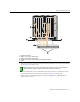
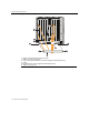
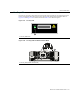
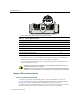
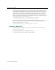
Figure 3-39 Fan Tray LEDs on Bottom Cable Management Assembly Base Panel
Thefollowingadditionalconditionsapply:
•Afterpowerup,thefantrayLEDremainsreduntildiagnosticsbegin,thenwillblinkgreen.
Whenblinkingamber,thefancontrollerwillrunadefaultconfiguration.
•Anoverheatingwarningindicatesfansarerunningathighspeed.Fansoperateatnormal
speedifnowarningis
received.
Module LEDs and Reset Button
Control and Fabric Module LEDs
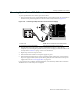
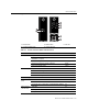
TwoLEDsareprovidedforCMsandFMs,STATUSandACTIVE/STANDBY,asshownin
Figure 3‐40.Additionally,Speed(10/100/1000Mbps)andStatusLEDsontheCMEthernetRJ45
portindicatea10,100,or1000Mbpslink.LEDdefinitionsareprovidedinTable 3‐3.
TheCMalsoprovidesaReset
buttonwhichwarm‐rebootsthemodule,suspendingserviceforthe
durationofthereboot.IftwoCMsareinstalledhowever,serviceisnotinterrupted.
1 Fan Tray LEDs (bottom cable management assembly base panel)
Table 3-2 Fan Tray LED Definitions
Function LED Activity
Fan tray functioning correctly Green
Fan tray not powered Off
Fan tray status during initialization and diagnostics Blinking green
Unit’s fan failed or module overheated but still provides enough cooling Amber
Unsupported configuration has been set from the CM Blinking amber
Fan tray failed and requires attention Red
Caution: If the LED remains red, replace the fan tray immediately. Otherwise, the system may
overheat and damage chassis components.
Precaución: Si observa que la lucecita roja no se apaga, cambie inmediatamente el sistema de
ventilación. Si no lo hace, el sistema se sobrecalentará y los componentes del chasis se dañarán.
1234 5678
1
FAN TRAY
2
FAN TRAY
3
FAN TRAY
STRAP
S/N: MAC ADD.
CM1 CM2
GROUND
1
FAN TRAY
2
FAN TRAY
3
FAN TRAY
STRAP
S/N: MAC ADD.
GROUND
1