
Network Router User's Manual


LEDs and Reset Button
3-42 Matrix X16-C Chassis Setup
LEDs and Reset Button
ThefollowingsectionsdescribeLEDindicationsforthefollowing:
•Powersuppliesandfantrays
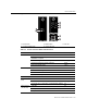
•IOM,CM,andFMs(withCMResetbutton)
Power Supply LEDs
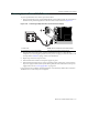
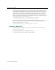
TwoLEDsareprovidedonthepowersupplymodule:aDCLEDindicatingtheoperationalstatus
ofoutgoingpowerandanACLEDindicatingincomingAClinevoltageissufficientorhasfallen
belowoperationallimits.RefertoFigure 3‐36fortheirlocationandTable 3‐1foradescriptionof
LED
function.PowersuppliesareinstalledinchassisslotsPS1throughPS6alongtheright‐hand
sideofthechassis.
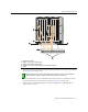
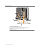
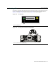
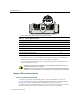
Figure 3-36 Power Supply LEDs
1 Intake cooling fans 2 DC Power LED 3 Handle 4 AC Power LED
342
1
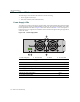
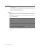
Table 3-1 DC/AC Power Supply (PS1-PS6) LED Definitions
Function LED Activity
DC Power LED
Power supply successfully providing 48 VDC to the system Green
Power supply malfunctioning Off
AC Power LED
Sufficient AC power supply (influx) Green
No AC power into the module Off