
Network Router User's Manual

Installing and Removing Modules
Matrix X16-C Chassis Installation Guide 3-23
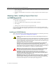
Installing and Removing CMs
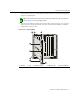
1. LocatetheemptyCM1slot,andpositionthemoduleintheguiderailattheleftoftheslot,as
showninFigure 3‐22.Gentlyinsertthemoduleuntilitengages with thebackplane
connectors.BesuretheejectorhandlesareopenasshowninFigure 3‐20.
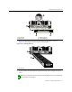
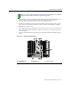
2. Pushtheejector
handlestowardthecenterofthe module,asshowninFigure 3‐20,engaging
thelipoftheslot,untilthemodulelocksintoplaceandisflushwithadjoiningcoverplates.
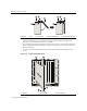
3. Tightenthetwocaptivescrews.
4. Aftercompletingallmoduleinstallation,besurethatyouleavenoslotsuncovered.Failureto
seal
anyemptyslotswiththeprovidedcoverplatesmayhamperpowercoolingofthechassis
anditscomponents.
5. ToremoveaninstalledCM,firstdisconnectanycablingandperformtheinstallationstepsin
reverse.
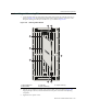
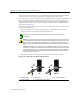
Figure 3-22 Installing Control Module
Note: If you ordered the Memory Upgrade Kit (X-4G-MEM), install the DIMMs first. For installation
instructions, refer to “Installing the Memory Upgrade Kit” on page 3-35.
1 Control Module slot 1 3 Guide rails 5 Captive screws (2)
2 Control Module 4 Ejector handles (2)
5
12 3 67845
FAN TRAY
2
FAN TRAY
3
1
FAN TRAY
STRAP
S/N: MAC ADD.
CM1 CM2
GROUND
STATUS
ACTIVE/
STANDBY
RESET
USB
ETHERNET
COM
TX
RX
TX
RX
TX RX TX RX
5
1
3
3
2
5
4
4