
Network Router User's Manual
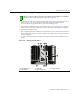

Installing and Removing Modules
3-22 Matrix X16-C Chassis Setup
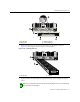
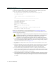
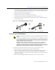
Figure 3-20 Engaging Ejector Handles
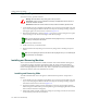
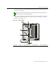
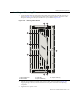
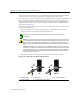
7. Toinstalladditionalmodules,removethecoverplatesfromtheslots,asshowninFigure 3‐21,
andrepeatearliersteps.Savecoverplatesforoptionalfutureuse.NotethatIOMslots7
through16areprotectedbydouble‐widecoverplates.
8. Aftercompletingallmoduleinstallation,besurethatyouleavenoslots
uncovered.Failureto
sealanyemptyslotswiththeprovidedcoverplatesmayhamperpowercoolingofthechassis
anditscomponents.
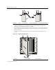
9. ToremoveaninstalledIOM,firstdisconnectanycablingandperforminstallationstepsin
reverse.
Figure 3-21 Removing IOM Coverplate
1 Module 2 Slot 3 Chassis rail 4 Ejector handle (open) 5 Ejector handle (closed)
1 IOM slot 2 2 IOM coverplate 3 Captive screws (2)
1
2
3
5
1
2
3
4
12 3 67845
FAN TRAY
2
FAN TRAY
3
1
FAN TRAY
3 4
1
FAN TRAY
2
FAN TRAY
STATUS
TX
RX
TX
RX
TX RX TX RX
X-M2-00
10G ENET
MAC ADD.
S/N:
STRAP
S/N: MAC ADD.
CM1 CM2
GROUND
3
1 3
2