
Network Router User's Manual

Installing and Removing a Power Supply
Matrix X16-C Chassis Installation Guide 3-17
12. Replacethepowersupplyventplate.
Removing a Power Supply
Toremoveapowersupply,proceedasfollows:
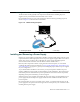
1. Attachtheanti‐staticwriststrapasdescribedin“AttachingtheElectrostaticDischargeWrist
Strap”onpage 3‐13beforehandlingthepowersupplymodule.
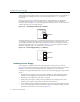
2. Unplugtheassociatedpowercordfromthe20A/100‐125Vac(or8A/200‐240Vac)outlet.
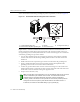
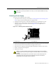
3. Unplugthepowercord
fromtheACinlet(associatedwiththepowersupplyyouare
removing)atthebackofthechassis,asshowninFigure 3‐16.Forexample,inletAC1
correlateswithPS1.
Figure 3-16 Removing the AC Inlet Power Cord
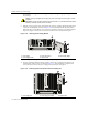
4. Loosenscrewssecuringthepowersupplyventplatetothechassisandremovetheventplate.
5. Unscrewthecaptivescrew
toreleasethepowersupplyfromthechassis.
6. Removethepowersupplybygraspingthehandleandpullingitstraightoutofthechassis.
7. Fastenacoverplateovertheemptyslot.
8. Reinstalltheventplate.
Note: Before you power up the Matrix X16-C chassis, you must complete installation of fan trays
and modules.
1 Inlet power cord 2 AC inlet (AC1)
Caution: If you plan to operate the chassis with only one power supply, be sure to install the
coverplate in place of the removed power supply to contain EMI radiation and ensure proper air
circulation.
Precaución: Si desea trabajar sólo con una fuente de poder, no olvide colocar la tapa en el
compartimiento de la fuente de poder que haya eliminado, para reducir la interferencia
electromagnética y para asegurar una buena ventilación.
AC INLET 2
100-125V-20A
200-240V-8A
50/60Hz
AC INLET 1
100-125V-20A
200-240V-8A
50/60Hz
2
1