
Network Router User's Manual

Installing and Removing a Power Supply
3-16 Matrix X16-C Chassis Setup
8. Positionthepowersupplywiththeflangeandcaptivescrewpointingupandalignwiththe
slotopening.
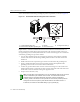
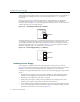
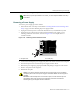
9. Withthepowersupplyproperlyinsertedintotheopening,carefullyslidethemoduleuntilit
connectstothebackplane,asshowninFigure 3‐14.Themodule’shandleshouldbenearly
flushwiththe
faceoftheMatrixX16‐Cchassis.Ifsignificantresistanceisencounteredbefore
thepowersupplyisseated,removeandreinsertit.Donotforcethemoduleintoplace.
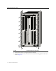
Figure 3-14 Installing Power Supply Module
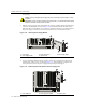
10. Securethepowersupplytothechassisbytighteningthecaptivescrew.
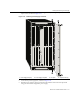
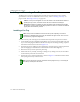
11. Ifyouareinstallingadditionalpowersupplies,removethecoverplates
fromtheirslotsby
looseningtheircaptivescrews,asshowninFigure 3 ‐15,(keeptheblankcoverplateinthe
eventyouneedtoremovethepowersupply)andrepeatsteps7through10.
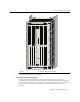
Figure 3-15 Removing Blank Coverplate from Power Supply Slot
Caution: Forcing a misaligned power supply into place can damage the power supply or chassis
backplane.
Precaución: Colocar de manera forzada una fuente de poder o no colocarla bien alineada podría
dañarla y/o maltratar el panel posterior del chasis.
1 Power supply 3 Power supply slot 1 5 Power supply flange
2 Power supply handle 4 Captive screw
1 Power supply slot 2 Power supply coverplate 3 Captive screw
12 3 67845
FAN TRAY
2
FAN TRAY
3
1
STRAP
S/N: MAC ADD.
CM1 CM2
GROUND
FAN TRAY
3
1
2
4
5
STRAP
S/N: MAC ADD.
CM1 CM2
GROUND
1
3
2
12 3 67845
FAN TRAY
2
FAN TRAY
3
1
FAN TRAY