Enterasys Matrix™ X Secure Core Router X16-C Chassis Installation Guide P/N 9034082-04
Electrical Hazard: Only qualified personnel should perform installation procedures. Riesgo Electrico: Solamente personal calificado debe realizar procedimientos de instalacion. Elektrischer Gefahrenhinweis: Installationen sollten nur durch ausgebildetes und qualifiziertes Personal vorgenommen werden. Notice Enterasys Networks reserves the right to make changes in specifications and other information contained in this document and its web site without prior notice.
Regulatory Compliance Information Federal Communications Commission (FCC) Notice This device complies with Part 15 of the FCC rules. Operation is subject to the following two conditions: (1) this device may not cause harmful interference, and (2) this device must accept any interference received, including interference that may cause undesired operation. NOTE: This equipment has been tested and found to comply with the limits for a class A digital device, pursuant to Part 15 of the FCC rules.
Electromagnetic Compatibility (EMC) This product complies with the following: 47 CFR Parts 2 and 15, CSA C108.8, 89/336/EEC, EN 60825, EN 55022, EN 61000‐3‐2, EN 61000‐3‐3, EN 55024, AS/NZS CISPR 22, CFR 1040.10, VCCI V‐3. Compatibilidad Electromágnetica (EMC) Este producto de Enterasys cumple con lo siguiente: 47 CFR Partes 2 y 15, CSA C108.8, 89/336/EEC, EN 60825, EN 55022, EN 55024, EN 61000‐3‐2, EN 61000‐3‐3, AS/NZS CISPR 22, CFR 1040.10, VCCI V‐3.
ѻક䇈ᯢк䰘ӊ Supplement to Product Instructions 䚼ӊৡ⿄ (Parts) 䞥ሲ䚼ӊ (Metal Parts) ⬉䏃ഫ (Circuit Modules) ⬉㓚ঞ⬉㓚㒘ӊ (Cables & Cable Assemblies) ล᭭㘮ড়⠽䚼ӊ (Plastic and Polymeric parts) ⬉䏃ᓔ݇ (Circuit Breakers) ƻ˖ 䪙 3E ᳝↦᳝ᆇ⠽䋼ܗ㋴ (Hazardous Substance) ⒈㘨㣃 ∲ 䬝 ݁Ӌ䫀 3%% +J &G &U h ƻ ƻ h ƻ ƻ h ƻ ƻ h ƻ ƻ h ƻ ƻ h ƻ ƻ ƻ ƻ ƻ ƻ ƻ h ƻ ƻ h h ƻ ƻ ⒈Ѡ㣃䝮 3%'( 㸼⼎䆹᳝↦᳝ᆇ⠽䋼䆹䚼ӊ᠔᳝ഛ䋼ᴤ᭭Ёⱘ䞣ഛ SJ/T 11363-2006 ᷛޚ㾘ᅮⱘ䰤䞣㽕∖ҹϟDŽ Indicates that the concentration of the hazardous substance
VCCI Notice This is a class A product based on the standard of the Voluntary Control Council for Interference by Information Technology Equipment (VCCI). If this equipment is used in a domestic environment, radio disturbance may arise. When such trouble occurs, the user may be required to take corrective actions. BSMI EMC Statement — Taiwan This is a class A product. In a domestic environment this product may cause radio interference in which case the user may be required to take adequate measures.
Declaration of Conformity Application of Council Directive(s): 89/336/EEC 73/23/EEC Manufacturer’s Name: Enterasys Networks, Inc. Manufacturer’s Address: 50 Minuteman Road Andover, MA USA 01810 European Representative Address: Conformance to Directive(s)/Product Standards: Equipment Type/Environment: Enterasys Networks, Ltd.
Enterasys Networks, Inc. Firmware License Agreement BEFORE OPENING OR UTILIZING THE ENCLOSED PRODUCT, CAREFULLY READ THIS LICENSE AGREEMENT. This document is an agreement (“Agreement”) between the end user (“You”) and Enterasys Networks, Inc.
4. EXPORT RESTRICTIONS. You understand that Enterasys and its Affiliates are subject to regulation by agencies of the U.S. Government, including the U.S. Department of Commerce, which prohibit export or diversion of certain technical products to certain countries, unless a license to export the Program is obtained from the U.S. Government or an exception from obtaining such license may be relied upon by the exporting party.
10. ENFORCEMENT. You acknowledge and agree that any breach of Sections 2, 4, or 9 of this Agreement by You may cause Enterasys irreparable damage for which recovery of money damages would be inadequate, and that Enterasys may be entitled to seek timely injunctive relief to protect Enterasys’ rights under this Agreement in addition to any and all remedies available at law. 11. ASSIGNMENT.
x
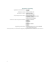
Contents About This Guide Who Should Use This Guide ........................................................................................................................... xv Using This Guide ............................................................................................................................................. xv Using the Matrix X Router Manual Set ............................................................................................................
Attaching Cables, Installing Compact Flash Card and DIMM Upgrade Kit ................................................... 3-26 Installing an XFP/SFP Module ............................................................................................................... 3-26 Removing an XFP/SFP Module ............................................................................................................. 3-27 Connecting Fiber-Optic Cables ....................................................................
Figures 1-1 1-2 3-1 3-2 3-3 3-4 3-5 3-6 3-7 3-8 3-9 3-10 3-11 3-12 3-13 3-14 3-15 3-16 3-17 3-18 3-19 3-20 3-21 3-22 3-23 3-24 3-25 3-26 3-27 3-28 3-29 3-30 3-31 3-32 3-33 3-34 3-35 3-36 3-37 3-38 3-39 3-40 A-1 Matrix X16-C Chassis as Shipped (Front View) ................................................................................. 1-2 Matrix X16-C Chassis as Shipped (Rear View) .................................................................................. 1-3 Disassembly Steps 1 and 2 ............
Tables 3-1 3-2 3-3 3-4 A-1 A-2 A-3 A-4 A-5 A-6 A-7 A-8 A-9 A-10 A-11 A-12 A-13 A-14 A-15 A-16 A-17 A-18 A-19 A-20 A-21 xiv DC/AC Power Supply (PS1-PS6) LED Definitions ........................................................................... 3-42 Fan Tray LED Definitions ................................................................................................................. 3-44 Control and Fabric Module LED Definitions ...........................................................................
About This Guide This guide describes the Enterasys Matrix™ X16‐C chassis features, options, specifications, and provides information to install the chassis in a standard 19‐inch (48.26‐centimeter) equipment rack or cabinet. This guide also explains how to interpret the system status LEDs to facilitate troubleshooting when necessary, and provides information on how to contact Enterasys Networks if you need help.
Using the Matrix X Router Manual Set Using the Matrix X Router Manual Set Additional documents are provided to explain installation of X Router Input/Output Modules (IOMs) in the X16‐C, configuration of CLI commands on the X16‐C and how to apply these commands with more in‐depth instructions, how to respond to error messages that may appear on the command line, and advise you on the latest Release Notes.
Commonly Used Acronyms Commonly Used Acronyms The following acronyms are used extensively throughout this guide: • IOM – Input/Output Module • FM – Fabric Module • CM – Control Module • LED – Light Emitting Diode • XFP – 10‐Gigabit Small Form Factor Pluggable fiber‐optic transceiver • SFP – 1‐Gigabit Small Form Factor Pluggable fiber‐optic transceiver • SMF – Single Mode Fiber • MMF – Multimode Fiber • WWDM – Wide‐Wavelength‐Division Multiplexed • USB – Universal Serial Bus • ESD – Ele
Getting Help xviii About This Guide
1 Overview This chapter describes the following: For information about: Refer to page ... System Description 1-1 Features 1-4 System Description The Matrix X16‐C design provides 20 slots to seat 16 Input/Output Modules (IOM), two Fabric Modules (FM), and two Control Modules (CM). The Matrix X16‐C supports: • Terabit switching capacity • Hot swapping of modules • Redundant power and cooling systems • Installation in a standard 19‐inch (48.26‐centimeter) wide rack.
System Description Figure 1-1 Matrix X16-C Chassis as Shipped (Front View) 1 2 FAN TRAY FAN TRAY FAN TRAY 5 4 9 10 11 12 13 3 FM1 FM2 CM1 CM2 3 14 15 16 6 7 8 4 5 6 7 8 9 10 1 2 3 4 5 1-2 Overview GROUND S/N: 1 FAN TRAY 1 2 3 4 STRAP MAC ADD.
System Description Figure 1-2 Matrix X16-C Chassis as Shipped (Rear View) AC INLET 6 100-125V-20A 200-240V-8A 50/60Hz AC INLET 5 100-125V-20A 200-240V-8A 50/60Hz AC INLET 4 100-125V-20A 200-240V-8A 50/60Hz 1 CAUTION: THIS UNIT MAY HAVE MORE THAN ONE POWER SUPPLY CORD. DISCONNECT SIX (6) POWER SUPPLY CORDS BEFORE SERVICING TO AVOID ELECTRIC SHOCK. VORSICHT: DIESES GERÄT HAT MEHR ALS EINEN NETZANSSCHLUß.
Features Features The following sections provide an overview of the system features. X16-C Input/Output Modules The Matrix X16‐C supports Input/Output Modules (IOM) which perform all system packet forwarding. The X16‐C provides 16 slots to install the IOMs.
Features (ACLs) and, by default, is associated with the VPN Routing/Forwarding (VRF) instance that all interfaces are assigned to. Be aware of the following caveats, however, when using this interface: • IGP and EGP routing protocols do not export routes • Bridging is not supported The Console port is considered the primary CLI interface, and is also useful for reading startup and diagnostic messages, event logging, and many other tasks.
Features 5. Insert the standby CM into the system and wait until it is fully synchronized with the active CM before removing the active CM. Do not physically remove the active CM during the synchronization process. The following message will appear on your console screen: MXS Standby: Synchronization monitoring system MXS CM Standby: SYNCING DATA. Do not remove the Active CM configuration data 124 MB high-availability data256 MB 6. Copying 10.
Features 7. Again, you can enter the show system high‐availability command to verify synchronization is complete and the standby CM is up. Note in the output that the Standby Module status has changed from Synchronizing to In‐Service.
Features X16-C Redundant Power Supplies The Matrix X16‐C supports up to six power supplies that install on the right side of the chassis, in slots labeled PS1 through PS6. While the chassis can operate with fewer than six power supplies installed depending upon the number of installed IOMs, FMs, and CMs, additional power supplies provide redundancy and load sharing. Each power supply (X‐AC) requires a dedicated 100‐240 Vac, 20 Amp earth‐grounded circuit.
Features Rack-Mountable Chassis The Matrix X16‐C chassis is designed to be mounted in a standard 19‐inch wide (48.26‐centimeter) equipment rack. You can load two chassis into a standard 7‐foot high (213.36‐centimeter) rack. Optional bottom shelving and mid‐mount brackets are available for non‐standard circumstances. Refer to “Site Guidelines” on page 2‐1 for requirements on ventilation and cooling.
Features 1-10 Overview
2 Site and Configuration Guidelines This chapter describes the following: For information about: Refer to page ... Site Guidelines 2-1 Configuration Guidelines 2-2 Electrical Hazard: Only qualified personnel should install or service this unit. Riesgo Eléctrico: Solamente personal capacitado debe de instalar o darle servicio a esta unida. Elektrischer Gefahrenhinweis: Installationen oder Servicearbeiten sollten nur durch ausgebildetes und qualifiziertes Personal vorgenommen werden.
Configuration Guidelines Configuration Guidelines The Matrix X16‐C provides 20 slots that accept modules. IOM (Input/Output Module) slots are numbered 1 through 8 beginning with the bottom left‐most slot and continuing from 9 through 16 beginning at the top left. Two Fabric Module slots, labeled FM1 and FM2, are located in the middle of the chassis, and beneath them, Control Module slots CM1 and CM2. The three slots located at the very bottom of the chassis are reserved for fan trays.
3 Matrix X16-C Chassis Setup This chapter describes the following: For information about: Refer to page ...
Unpacking the Matrix X16-C Chassis Unpacking the Matrix X16-C Chassis Note: Unpack the Matrix X16-C chassis components only as needed. Leave the components in their respective shipping cartons until you are ready to install that component. Save all shipping materials in the event you must repack the chassis. The Matrix X16‐C chassis is packed and shipped on a skid. Before unpacking the chassis, examine the outside packaging for obvious damage.
Unpacking the Matrix X16-C Chassis Figure 3-2 Disassembly Steps 3 and 4 7 1 2 3 4 6 5 1 2 3 4 5. Accessory package Screw assemblies packet ESD wrist strap packet Documentation 5 RJ45 management cable 6 Styrofoam cap 7 Rack support brackets Open the top of the shipping bag covering the unit, then pull the bag down around the skid, as shown in Figure 3‐3. Figure 3-3 Disassembly Step 5 1 2 1 Shipping bag 3 1 2 Shipping skid 3 Chassis 6.
Unpacking the Matrix X16-C Chassis Figure 3-4 Disassembly Steps 6 through 8 1 3 4 4 3 2 1 Chassis 2 Shipping bag and skid 9. 3 Shipping screws (10) 4 Shipping brackets (4) Be aware that the following peripherals ship separately: – IOMs – CMs – FMs – Fan trays – Power supplies and 20‐Amp line (inlet) cords (one per power supply) – Power cords with twist lock plugs – Mid‐mount brackets (2) Note: To reship the chassis, refer to the directions above and reverse each step.
Setting Up the Matrix X16-C Chassis Setting Up the Matrix X16-C Chassis The following sections describe the procedures that must be followed to complete chassis installation. Chassis are shipped with all slots labeled “1” open. Coverplates over IOM slot 1, Fabric and Control Module slot 1, Fan Tray slot 1, and PS1 (power supply) are removed, and the slots are ready for module installation. Setup Order Once a suitable site has been chosen, proceed to install the Matrix X16‐C chassis in a rack.
Setting Up the Matrix X16-C Chassis Installing Optional Rack Support Brackets Rack support brackets are shipped with the chassis to provide additional support underneath the chassis. Use of these brackets is recommended for installations with four‐post cabinets to augment standard rack support by the front ears on the chassis.
Setting Up the Matrix X16-C Chassis Figure 3-5 Installing Rack Support Brackets 3 3 1 2 1 Rack 2 Rack support brackets (2) 2 1 3 Bracket screws (16) Installing Optional Mid-Mount Brackets You can purchase an optional mid‐mount bracket kit for a rack or cabinet where the standard front‐chassis ear attachment is unusable due to space concerns.
Setting Up the Matrix X16-C Chassis Figure 3-6 Fastening Mid-Mount Brackets FAN TRAY FAN TRAY 9 10 11 FAN TRAY 12 13 FM1 14 15 16 FM2 2 2 CM1 CM2 GROUND S/N: 1 FAN TRAY 1 2 3 4 STRAP MAC ADD.
Setting Up the Matrix X16-C Chassis Rack Mounting the Matrix X16-C Chassis Note: Read Chapter 2, Site and Configuration Guidelines, before completing the following procedure to ensure that all installation guidelines are met. To rack‐mount the Matrix X16‐C chassis, proceed as follows: Warning: We recommend you use a forklift or other mechanical device to lift and hold the chassis.
Setting Up the Matrix X16-C Chassis Figure 3-7 Rack Mounting the Matrix X16-C Chassis FAN TRAY FAN TRAY FAN TRAY 5 4 9 10 11 12 13 FM1 FM2 CM1 CM2 3 14 15 16 6 7 8 GROUND S/N: 1 FAN TRAY 1 Á 2 3 4 STRAP MAC ADD. 5 FAN TRAY FAN TRAY 2 3 Á À 1 Rack 3-10 À 2 Rack-mounting screws (8 per side) 3. Lift the chassis onto the rack support brackets (if installed). 4.
Setting Up the Matrix X16-C Chassis Figure 3-8 Rack Mounting the Mid-Mounted Chassis 1 1 FAN TRAY FAN TRAY FAN TRAY 5 4 9 10 11 12 13 FM1 FM2 CM1 CM2 3 14 15 16 6 7 8 GROUND S/N: 1 FAN TRAY 1 2 3 STRAP 4 MAC ADD. 5 FAN TRAY FAN TRAY 2 3 2 1 Rack 5. 2 Rack-mounting screws (8 per side) Chassis rack mounting is now complete.
Setting Up the Matrix X16-C Chassis To meet these requirements, use the four tapped holes located on the rear‐center side of the chassis. These holes meet the hole grounding bolt pattern requirements, as shown in Figure 3‐9.
Installing and Removing a Power Supply Attaching the Electrostatic Discharge Wrist Strap The Electrostatic Discharge (ESD) wrist strap must be attached before handling the power supplies, fan tray, and modules used in the Matrix X16‐C chassis. Place the ESD wrist strap on your wrist and plug the other end into the grounding receptacle, shown in Figure 3‐10, near the bottom of the chassis. Figure 3-10 ESD Grounding Receptacle CM1 CM2 GROUND 1 S/N: STRAP MAC ADD.
Installing and Removing a Power Supply Power Supply Planning Although each power supply requires its own circuit, when planning the X16‐C power budget you have the option of drawing from one or more sources by either the N + 1 or 1 + 1 method, respectively. Drawing power by the N + 1 method protects the X16‐C against the failure of a single power source although not against an outage by that source.
Installing and Removing a Power Supply 5. Remove the vent plate covering all power supply slots by loosening the top and bottom captive screws, as shown in Figure 3‐13. Figure 3-13 Removing Power Supply Vent Plate 2 FAN TRAY FAN TRAY 10 11 4 FAN TRAY 5 4 9 12 13 FM1 FM2 CM1 CM2 3 14 15 16 6 7 8 3 GROUND S/N: 1 FAN TRAY 1 2 3 4 STRAP MAC ADD. 5 FAN TRAY FAN TRAY 2 3 1 4 1 Power supply slot (PS1) 2 Power supply coverplate 3 Vent plate 4 Captive screws (2) 6.
Installing and Removing a Power Supply 8. Position the power supply with the flange and captive screw pointing up and align with the slot opening. Caution: Forcing a misaligned power supply into place can damage the power supply or chassis backplane. Precaución: Colocar de manera forzada una fuente de poder o no colocarla bien alineada podría dañarla y/o maltratar el panel posterior del chasis. 9.
Installing and Removing a Power Supply 12. Replace the power supply vent plate. Note: Before you power up the Matrix X16-C chassis, you must complete installation of fan trays and modules. Removing a Power Supply To remove a power supply, proceed as follows: 1. Attach the anti‐static wrist strap as described in “Attaching the Electrostatic Discharge Wrist Strap” on page 3‐13 before handling the power supply module. 2. Unplug the associated power cord from the 20A/100‐125 Vac (or 8A/200‐240 Vac) outlet.
Installing and Removing a Fan Tray Installing and Removing a Fan Tray The Matrix X16‐C chassis is equipped with removable fan trays that allow for easy periodic replacement if a fan fails. To install and remove a fan tray, refer to “Installing a Fan Tray” on page 3‐18 and “Removing a Fan Tray” on page 3‐20. Caution: A fan tray is hot-swappable. Do not run the chassis for an extended interval without an operating fan tray, however, because the chassis will soon overheat and be damaged.
Installing and Removing a Fan Tray Figure 3-17 Removing Bottom Bezel 4 CM1 CM2 GROUND S/N: STRAP MAC ADD. 1 2 1 FAN TRAY 2 3 4 5 6 FAN TRAY 1 7 8 FAN TRAY 2 3 3 1 Fan tray slot 1 2 Bottom bezel 6. 3 3 Captive screws (2) 4 Fan tray flanges (2) Slowly slide the fan tray into the open slot at the bottom of the chassis, as shown in Figure 3‐18, until it engages with the connector on the backplane. Figure 3-18 Installing Fan Tray CM1 CM2 GROUND S/N: STRAP MAC ADD.
Installing and Removing Modules Removing a Fan Tray To remove a fan tray, proceed as follows: Warning: Allow fan blades to stop running prior to fan tray removal. Advertencia: Espere a que los ventiladores se detengan completamente antes de remover el sistema de ventilacion del chasis. Warnhinweis: Warten sie mit dem Ausbau der Lüfter, bis diese zum Stehen gekommen sind. 1. Locate the ESD wrist strap shipped with the Matrix X16‐C chassis.
Installing and Removing Modules 4. Locate Slot #1 at the bottom left side of the chassis and insert the IOM in the guide rail of the slot, as shown in Figure 3‐19. Gently slide the module into the rack until the IOM engages the connector on the backplane. Note: As you insert the IOM into the slot, be sure the ejector handles are in the open position, as shown in Figure 3-20, to avoid damaging the IOM. 5.
Installing and Removing Modules Figure 3-20 Engaging Ejector Handles 2 3 2 4 1 1 Module 3 5 1 2 Slot 3 Chassis rail 4 Ejector handle (open) 5 Ejector handle (closed) 7. To install additional modules, remove the coverplates from the slots, as shown in Figure 3‐21, and repeat earlier steps. Save coverplates for optional future use. Note that IOM slots 7 through 16 are protected by double‐wide coverplates. 8.
Installing and Removing Modules Installing and Removing CMs Note: If you ordered the Memory Upgrade Kit (X-4G-MEM), install the DIMMs first. For installation instructions, refer to “Installing the Memory Upgrade Kit” on page 3-35. 1. Locate the empty CM1 slot, and position the module in the guide rail at the left of the slot, as shown in Figure 3‐22. Gently insert the module until it engages with the backplane connectors. Be sure the ejector handles are open as shown in Figure 3‐20. 2.
Installing and Removing Modules Replacing the CM Battery If the Panasonic lithium battery on the CM is failing, the system will operate properly until a power cycle, then an error message displays (see example, below): Enterasys Networks Copyright 1985-2002 Phoenix Technologies Ltd. All Rights Reserved * E7501 & Banias Rev #1.
Installing and Removing Modules Installing and Removing FMs 1. Locate the empty FM1 slot and position the module in the guide rail at the left of the slot, as shown in Figure 3‐23. Gently insert the module until it engages with the connectors on the backplane, making sure the ejector handles are open, as shown in Figure 3‐20.
Attaching Cables, Installing Compact Flash Card and DIMM Upgrade Kit 4. After completing all module installation, be sure that you leave no slots uncovered. Failure to seal any empty slots with the provided coverplates may hamper power cooling of the chassis and its components. 5. To remove an installed FM, first disconnect any cabling and perform the installation steps in reverse.
Attaching Cables, Installing Compact Flash Card and DIMM Upgrade Kit To install an XFP/SFP transceiver, refer to Figure 3‐24 and proceed as follows: 1. Locate the ESD wrist strap shipped with the Matrix X16‐C chassis. Attach the ESD wrist strap to your wrist and plug the cable from the ESD wrist strap into the ESD grounding receptacle at the bottom of the chassis as shown in Figure 3‐10. 2. Remove the transceiver from its packaging. 3. Hold the transceiver so that the connector will seat properly. 4.
Attaching Cables, Installing Compact Flash Card and DIMM Upgrade Kit Connecting Fiber-Optic Cables This section describes connecting 10‐ or 1‐Gigabit Ethernet fiber‐optic segments from the network or other devices to XFP or SFP port connectors (LC or MT‐RJ) on Matrix X16‐C IOMs. Each fiber‐optic link consists of two fiber‐optic strands within the cable: Transmit (TX) and Receive (RX).
Attaching Cables, Installing Compact Flash Card and DIMM Upgrade Kit 3. Plug the other end of the cable into the appropriate port on the other device. Some cables may be terminated at the other end with two separate connectors, one for each fiber‐optic strand. In this case, ensure that the transmit fiber‐optic strand is connected to the receive port and the receive fiber‐optic strand to the transmit port. 4. To verify link exists, you must first configure the ports for switching or routing.
Attaching Cables, Installing Compact Flash Card and DIMM Upgrade Kit 5. Connect the X16‐C’s power cords. Refer to “Powering Up the Matrix X16‐C Chassis” on page 3‐41.
Attaching Cables, Installing Compact Flash Card and DIMM Upgrade Kit Figure 3-27 Connecting a VT Series Terminal STATUS ACTIVE/ STANDBY RESET USB ETHERNET 2 4 1 UTP cable with RJ45 connectors 2 RJ45 COM port 3 COM 1 3 RJ45-to-DB25 VT adapter 4 VT series terminal Connecting the CM COM Port to a Modem To connect a modem to the CM COM port (Figure 3‐28), use a UTP cable with RJ45 connectors and a user‐supplied RJ45‐to‐DB25 male adapter, and proceed as follows: 1.
Attaching Cables, Installing Compact Flash Card and DIMM Upgrade Kit Figure 3-28 Connecting to a Modem STATUS ACTIVE/ STANDBY RESET USB ETHERNET 2 6 5 4 1 UTP cable with RJ45 connectors 2 RJ45 COM port 3 RJ45-to-DB25 modem adapter 3 COM 1 4 Local modem 5 Remote modem 6 IBM PC or compatible device Adapter Wiring and Signal Assignments COM Port Adapter Wiring and Signal Diagram RJ45 DB9 Pin Conductor Pin Signal 1 Blue 2 Receive (RX) 4 Red 3 Transmit (TX) 5 Green 5 Ground (GRD
Attaching Cables, Installing Compact Flash Card and DIMM Upgrade Kit VT Series Port Adapter Wiring and Signal Diagram RJ45 DB25 Pin Conductor Pin Signal 4 Red 2 Transmit (TX) 1 Blue 3 Receive (RX) 6 Yellow 5 Clear to Send (CTS) 5 Green 7 Ground (GRD) 2 Orange 20 Data Terminal Ready 1 Pins 8 Pins 13 25 RJ45 Connector (Female) 1 14 DB25 Connector (Female) Modem Port Adapter Wiring and Signal Diagram RJ45 DB25 Pin Conductor Pin Signal 1 Blue 2 Transmit (TX) 2 Ora
Attaching Cables, Installing Compact Flash Card and DIMM Upgrade Kit Figure 3-29 Attaching a USB Device to the CM STATUS ACTIVE/ STANDBY RESET 2 USB 3 1 1 USB device 2 Control Module 3 USB port Installing a Compact Flash Card The Control Module provides an IDE port housing a 1 GB Flash memory card, as shown in Figure 3‐30. If the factory‐installed card fails or you want to install a new Type I Compact Flash card, simply pull the old card from its connector and insert the new card.
Attaching Cables, Installing Compact Flash Card and DIMM Upgrade Kit Installing the Memory Upgrade Kit Caution: Only qualified personnel should perform installation procedures. Precaución: Solamente personal calificado debe realizar procedimientos de instalacion. The following sections describe how to upgrade the Dual In‐line Memory Modules (DIMMs) on the X‐CM‐00 Control Module from 1 GB (two 512 MB DIMMs) to 4 GB using the two 2 GB SDRAM DIMMs included in the X‐4G‐MEM Memory Upgrade Kit.
Attaching Cables, Installing Compact Flash Card and DIMM Upgrade Kit 4. Push the connector arms away from the first DIMM, as shown in Figure 3‐32, and remove the DIMM. Figure 3-32 Removing the Existing DIMM 1 DIMM 5. 2 Connector fingers 3 Connector arms Repeat step 4 to remove the second DIMM. Installing the DIMMs Caution: Observe all Electrostatic Discharge (ESD) precautions when handling sensitive electronic equipment.
Optional Cable Management Kit Optional Cable Management Kit Cables can be kept neat and secure using the optional Cable Management Kit (X16‐CBLMG‐KIT). Using the Cable Management Kit ensures that cables are bundled close to the chassis and that cabling is not accidentally loosened or disconnected from the chassis during operation.
Optional Cable Management Kit Installing the Optional Cable Management Kit Note: The cable management assemblies must be removed to install fan trays. To install the Cable Management Kit, proceed as follows: 1. Unpack the top and bottom cable management assemblies from the shipping box. Examine each assembly. If either assembly is damaged, contact Enterasys Networks for instructions. 2.
Optional Cable Management Kit Figure 3-33 Installing the Bottom Cable Management Assembly 1 1 2 3 4 5 2 6 7 8 3 X16 1 2 3 4 5 4. Bottom chassis bezel Captive screws (2) (on chassis bezel) Bottom cable management assembly Captive screws (2) (on cable management assembly base panel) Cables Remove the bar of the cable management assembly by loosening the two captive screws on the bar. See Figure 3‐34 on page 3‐40. Note: Removing the bar from the cable management assembly is optional.
Optional Cable Management Kit Figure 3-34 Securing Cables Using Velcro Cable Straps X16 1 2 3 4 5 6 3-40 Bottom cable management assembly base panel Captive screws (2) on base panel Velcro cable straps (8 attached to each cable management assembly base panel) Cables Bar (attaches to the cable management assembly base panel) Captive screws (2) on bar Matrix X16-C Chassis Setup
Powering Up the Matrix X16-C Chassis Powering Up the Matrix X16-C Chassis To power up the Matrix X16‐C chassis, proceed as follows: 1. Plug one end of each power cord (included with the power supply) into the AC power inlet on the chassis back panel and tighten the cord lock bracket screw, as shown in Figure 3‐35.
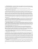
LEDs and Reset Button LEDs and Reset Button The following sections describe LED indications for the following: • Power supplies and fan trays • IOM, CM, and FMs (with CM Reset button) Power Supply LEDs Two LEDs are provided on the power supply module: a DC LED indicating the operational status of outgoing power and an AC LED indicating incoming AC line voltage is sufficient or has fallen below operational limits. Refer to Figure 3‐36 for their location and Table 3‐1 for a description of LED function.
LEDs and Reset Button Fan Tray LEDs Each fan tray provides a status LED on its front panel. Fan tray LEDs are provided on the chassis bezels (only bottom LEDs shown) and on the optional cable management assemblies. Refer to Figure 3‐37 and Figure 3‐38 for LED locations and Table 3‐2 for their description. Figure 3-37 Fan Tray LED STATUS ALLOW FAN BLADES TO STOP PRIOR TO FAN TRAY REMOVAL 1 1 Fan Tray Status LED Figure 3-38 Fan Tray LEDs on Bottom Chassis Bezel S/. 4.
LEDs and Reset Button Figure 3-39 Fan Tray LEDs on Bottom Cable Management Assembly Base Panel GROUND S/N: MAC ADD. STRAP FAN TRAY FAN TRAY FAN TRAY 1 2 3 1 CM1 CM2 GROUND S/N: 1 2 3 4 STRAP MAC ADD.
LEDs and Reset Button Figure 3-40 Fabric and Control Module LEDs and Reset Button STATUS 1 ACTIVE/ STANDBY 2 3 RESET 1 2 STATUS ACTIVE/ STANDBY ETHERNET 4 5 Fabric Module 1 STATUS LEDs 2 ACTIVE/STANDBY LEDs Table 3-3 Control Module 3 RESET button 4 10/100/1000 LED 5 Link LED Control and Fabric Module LED Definitions CM & FM LED State LED Activity Status Not powered Off Diagnostics failed, module requires attention, or state before initialization is complete Red LED blinks during in
LEDs and Reset Button The following additional conditions apply: • After module power up, the CM/FM STATUS LED will remain red until diagnostics begin then will blink green. • After module power up, the ACTIVE/STANDBY LED will initially indicate Standby state until it registers either the Active or Standby state. • When a link is not present, the Speed LED will be off. IOM LEDs All IOM cards include one Status LED for the card and Transmit and Receive or Link/Activity and Speed LEDs for each port.
First-Time Quick Configuration First-Time Quick Configuration This section describes the minimal configuration required to facilitate first‐time communications with the Matrix X16‐C. Consider the following: • Decide whether you will configure the Matrix X16‐C for switching (bridging) or routing: • If routing, assign an IP address to interface eth0 for management access. Refer to “Assigning an IP Address to eth0” on page 3‐47.
First-Time Quick Configuration Enabling NTP To configure NTP for the Matrix X16‐C, enter the following commands at the CLI prompt. The following commands enable the Matrix X16‐C either as an NTP client or server. Specify set ntp client broadcast to accept time synchronization from any NTP server and set ntp client unicast to accept time from a particular server. Alternatively, configure the Matrix X16‐C to accept time synchronization from a particular NTP server (the system must be in unicast mode).
A Specifications and Regulatory Compliance This appendix provides information about the following: For information about: Refer to page ...
Power Supply Requirements, Specifications, and Twist Lock Options Table A-1 Matrix X-16C Specifications (continued) Item Specification Fan Tray Dimensions 4.13 cm H x 12.7 cm W x 56.52 cm D 1.625 in. H x 5.0 in. W x 22.25 in. D Weight 3.31 kg (7.
Power Supply Requirements, Specifications, and Twist Lock Options Table A-3 Module Power Specifications @ 110 Vac / 220 Vac Module Power (Watts) Thermal Output (BTU/HR) CM 97 Watts 331.1 BTU/HR Fan tray 85 Watts 290.1 BTU/HR X4-FM 30 Watts 102.4 BTU/HR X8-FM 62 Watts 211.6 BTU/HR X16-FM 98 Watts 334.5 BTU/HR X-G32-00 155 Watts 520.0 BTU/HR X-GT16-00 105 Watts 358.3 BTU/HR X-M2-00 155 Watts 520.0 BTU/HR X-T32-00 155 Watts 520.
10-Gigabit Ethernet Transceiver Specifications (XFP) Matrix X16‐C twist lock power cord options are as follows: Table A-6 Twist Lock Power Cord Options Enterasys Part Number Twist Lock Plug Type Power Requirement Receptacle Type TL-20A-CORD NEMA L5-20P 110V 20A NEMA L5-20R TL-L615P-USCORD NEMA L6-15P 220V 15A NEMA L6-15R 10-Gigabit Ethernet Transceiver Specifications (XFP) The 10‐Gigabit XFP (10‐Gigabit Small Form Factor Pluggable) interface port slots on Matrix X Router IOMs can support vari
1-Gigabit Ethernet Transceiver Specifications (SFP) The following XFP specifications in Table A‐9 meet or exceed the IEEE 802.3ae‐2002 standard. Table A-9 Recommended Cable Types and Specifications Item Type Max. Reach Min. Reach1 Connector 10GBASE-LR-XFP SMF (Single Mode Fiber) 10 km (6.21 mi) 2 m (6.6 ft) LC 10GBASE-ER-XFP SMF (Single Mode Fiber) 40 km (24.85 mi)2 2 m (6.6 ft) with minimum of 5 dB attenuation LC 10GBASE-ZR-XFP SMF (Single Mode Fiber) 80 km (49.7 mi) 2 m (6.
SFP Input/Output Specifications SFP Input/Output Specifications Matrix X Router Ethernet port interfaces accept 1000BASE‐SX short wavelength or 1000BASE‐LX long wavelength fiber SFPs (see Table A‐10) and are hot swappable.
SFP Input/Output Specifications MGBIC-LC03 Specifications (1000BASE-SX) Table A-13 MGBIC-LC03 Optical Specifications Item 62.5/125 µm MMF 50/125 µm MMF Transmit Power (minimum) -9.5 dBm -9.5 dBm Transmit Power (maximum) -3 dBm -3 dBm Receive Sensitivity -20 dBm -20 dBm Link Power Budget1 (Multimode Only) 10.5 dBm 10.5 dBm 1. The maximum drive distance (up to 2 km) depends on the quality of the installed multimode fiber-optic cable segment.
SFP Input/Output Specifications MGBIC-08 Specifications (1000BASE-ELX) Table A-17 MGBIC-08 Optical Specifications Item 62.5 µm MMF 50 µm MMF 10 µm SMF Transmit Power (minimum) -0 dBm, min. +2 dBm, typical +5 dBm, max. Receive Sensitivity -24 dBm, min. -26 dBm, typical Maximum Input Power -3 dBm Link Power Budget1 (Full Duplex Only) 23 dB 28 dB, typical 1. The maximum drive distance (up to 70 km) depends on the quality of the installed single-mode fiber-optic cable segment.
COM Port Pinout Assignments COM Port Pinout Assignments The COM port is a serial communications port for local access to Local Management, as shown in Figure A‐1. Refer to Table A‐20 for the COM port pin assignments. Figure A-1 COM Port Pin Assignments 5 1 9 6 Pins 1 through 9 are numbered vertically from bottom to top, left to right.
Regulatory Compliance A-10 Specifications and Regulatory Compliance
Index Numerics 10-Gigabit Ethernet Transceiver Specifications (XFP) A-4 1-Gigabit Ethernet Transceiver Specifications (SFP) A-5 A AC Power LED description of 3-42 location on power supply 3-42 AC1 inlet link to PS1 3-17 view of 3-17, 3-41 ACTIVE/STANDBY LED description of 3-45 for CM and FM 3-44 indication for 3-46 Assigning an IP Address to eth0 CLI configuration steps 3-47 Attaching cables description of 3-26 to 3-33 Attaching LC or MT-RJ cable connectors 3-28 Attaching the electrostatic discharge wrist
Fan tray slot 1 view of 3-19 FCC Notice ii Fiber budget A-6 Firmware License Agreement vii First-time quick configuration 3-47 to 3-48 FM1 slot view of 3-25 without coverplate 3-25 G Getting help Contract number for xvii information for xvii RMA number xvii serial, revision numbers xvii H Hazardous Substances iii How to attach cables 3-26 to 3-33 How to connect to the CM USB Port 3-33 How to ground the chassis 3-11 to 3-12 How to install a compact flash card 3-34 How to install an XFP/SFP module 3-26 to 3
Notices BSMI EMC v Class 1 Laser Transceiver v Class A ITE ii Declaration of Conformity vi EMC iii FCC ii General ii Industry Canada ii Product Safety ii VCCI v NTP enabling of 3-48 O Optional cable management kit description of 3-38 P Physical properties of chassis A-1 Power supply description of 3-13 description of air flow 1-8 description of LEDs 3-42 installation of 3-14 location of vent plate 3-15 planning for 3-14 removal of 3-17 twist lock power cord for 1-8, 3-4, 3-41 twist lock power cord specifi
Index-4