
- Enterasys Network Adapter Hardware Installation Guide


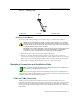
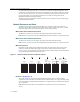
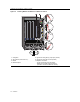
Table Of Contents
- Enterasys Matrix Hardware Installation Guide
- Notice
- Contents
- About This Guide
- Introduction
- Network Requirements
- Installation
- Troubleshooting
- Specifications
- Mode Switch Bank Settings and Optional Installations
- Index

Module Placement in a Matrix E7 Chassis
2-2 Network Requirements
Theuplinkshaveonefiber‐opticinterfacewithanLCconnector.DependingontheXFPandfiber‐
opticcableused,thesignalcanbedriventoamaximumdistanceof33 m(108ft)to40kilometers
(24.85miles).
Thedeviceattheotherendofthefiberopticconnectionmustbe
astandards‐compliantproduct
withamatchingXFPinterface.
Module Placement in a Matrix E7 Chassis
Ifyouwanttomix6x1xxx,6x2xxx,6x3xxx,and7x4xxxseriesmodulesinthesameMatrix
E7chassis,itisnecessarytohaveaDFE‐Diamondbridgingmoduleinstalled,andfollowthe
moduleplacementrulesdescribedin“BackplaneConnectionsandInstallationRules”onpage 3‐3
tosuccessfullybridgedatatrafficto
someorallmodulesinthechassis.