
- Enterasys Network Adapter Hardware Installation Guide
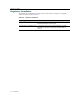
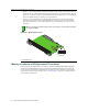
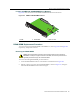
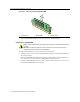
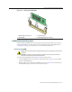
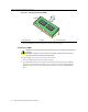
Table Of Contents
- Enterasys Matrix Hardware Installation Guide
- Notice
- Contents
- About This Guide
- Introduction
- Network Requirements
- Installation
- Troubleshooting
- Specifications
- Mode Switch Bank Settings and Optional Installations
- Index
Memory Locations and Replacement Procedures
B-6 Mode Switch Bank Settings and Optional Installations
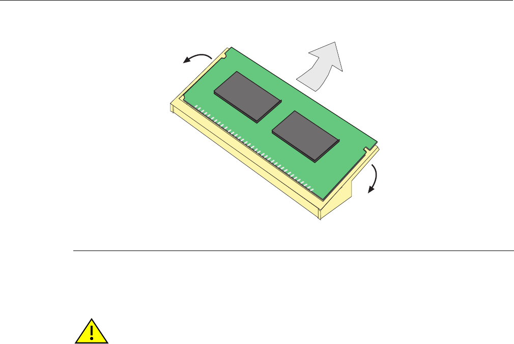
3. RotatetheDIMMupwards,thenremoveitfromtheconnectorfingers.
Installing the DIMM
ToinstallaDIMM,refertoFigure B‐6andproceedasfollows:
1. InserttheDIMMdownbetweentheconnectorfingers.
2. PivottheDIMMdownwardsothetabsontheconnectorarmsalignwiththetwoDIMM
alignmentnotches.Withthetwoconnectorarmsspreadoutward,pushtheDIMMdown
betweentheconnector
arms.ThenreleasethetwoconnectorarmstolocktheDIMMinto
place.
Figure B-5 Removing the Existing DIMM
1 Connector arms 2 DIMM 3 Connector fingers
Á
Â
À
À
Caution: Observe all Electrostatic Discharge (ESD) precautions when handling sensitive electronic
equipment.
Precaución: Al trabajar con equipos electrónicos sensibles, tome todas las precauciones de
seguridad para evitar descargas de electricidad estática.