
- Enterasys Network Adapter Hardware Installation Guide
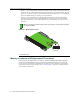
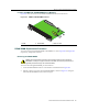
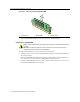
Table Of Contents
- Enterasys Matrix Hardware Installation Guide
- Notice
- Contents
- About This Guide
- Introduction
- Network Requirements
- Installation
- Troubleshooting
- Specifications
- Mode Switch Bank Settings and Optional Installations
- Index
Memory Locations and Replacement Procedures
Matrix DFE-Platinum Series Module Installation Guide B-3
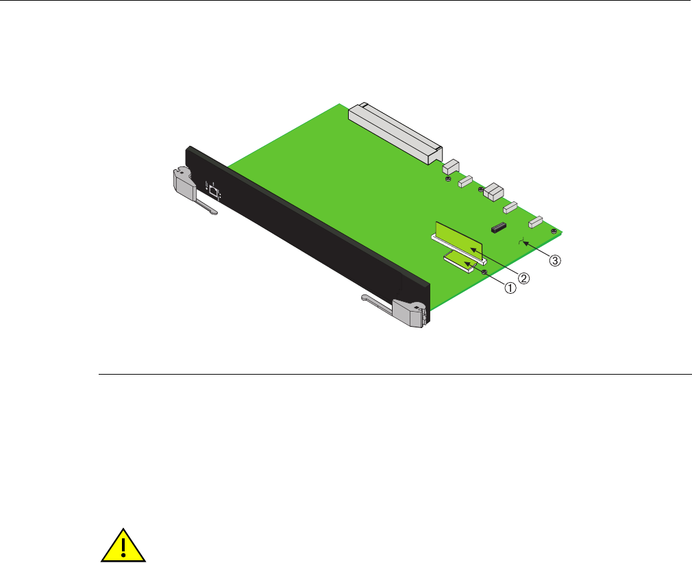
Location of DIMM and DRAM SIMM Memory Modules
Figure B‐2showsthelocationsoftheDIMMandDRAMSIMMonthemainboard.
DRAM SIMM Replacement Procedure
ToremoveandreplacetheDRAMSIMMonthe7KR4297‐xx,refertoFigure B‐3andFigure B‐4
respectively,andproceedasfollows:
Removing the DRAM SIMM
ToremovetheexistingDRAMSIMM,proceedasfollows:
1. LocatetheDRAMSIMMconnectoronthemainPCboard.ReferbacktoFigure B‐2.
2. PushtheconnectorarmsawayfromtheDRAMSIMM,asshowninFigure B‐3,enoughto
releasetheDRAMSIMMfromtheconnectorfingers.
Figure B-2 DIMM and DRAM SIMM Locations
1 DIMM 2 DRAM SIMM 3 Main PC board
Caution: Observe all antistatic precautions when handling sensitive electronic equipment.
Precaución: Al trabajar con equipos electrónicos sensibles, tome todas las precauciones de
seguridad para evitar descargas de electricidad estática.