
- Enterasys Network Adapter Hardware Installation Guide
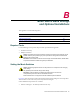
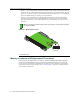
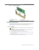
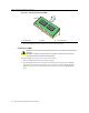
Table Of Contents
- Enterasys Matrix Hardware Installation Guide
- Notice
- Contents
- About This Guide
- Introduction
- Network Requirements
- Installation
- Troubleshooting
- Specifications
- Mode Switch Bank Settings and Optional Installations
- Index
Memory Locations and Replacement Procedures
B-2 Mode Switch Bank Settings and Optional Installations
•Switch7–ClearPersistentData.ChangingthepositionofthisswitchclearsPersistentDataon
thenextpower‐upofthemodule.Alluser‐enteredparameters,suchastheIPaddress,module
names,etc.,areresettothefactorydefaultsettings.Oncethemoduleresets,youcaneitheruse
the
factorydefaultsettingsorreenteryourownparameters.
•Switch8–ClearAdminPassword.Changingthepositionofthisswitchclearstheadmin
password,andrestoresthefactorydefaultpasswordonthenextpower‐upofthemodule.
Oncethemoduleresets,youcaneitherusethefactorydefaultsettingsor
reenteryourown
password.
Memory Locations and Replacement Procedures
IntheeventthattheDIMM(DualIn‐lineMemoryModule)orDRAMSIMM(DRAMSingleIn‐
lineMemoryModule)(FLASHmemory)needstobe replaced,thefollowingsectionsdescribe
howtoaccess,locateandrep lacethesememorymodules.Ifyouhavequestionsconcerningthe
replacementofeithermemorymodule,refer
to“GettingHelp”onpagexivfordetailsonhowto
contactEnterasys Networks.
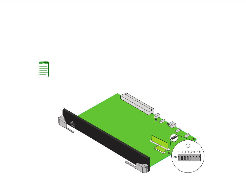
Note: Do not change the position of Switch 8 unless it is necessary to reset the admin password to
its factory default setting.
Figure B-1 Mode Switch Location
1 Mode switch bank