
- Enterasys Network Adapter Hardware Installation Guide
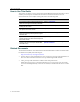
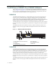
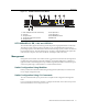
Table Of Contents
- Enterasys Matrix Hardware Installation Guide
- Notice
- Contents
- About This Guide
- Introduction
- Network Requirements
- Installation
- Troubleshooting
- Specifications
- Mode Switch Bank Settings and Optional Installations
- Index
Management
Matrix DFE-Platinum Series Module Installation Guide 1-3
Figure 1-2 7KR4297-04 DFE-Diamond Module
XFP 10GBASE-LR, -ER, -LX4, and -SR PHYS
TheLANXFPPHYs(physicalinterfaces)provideinexpensive,high‐speedEthernetconnectivity.
ThesePHYsprovidenetworkmanagerstheabilitytouse10‐GigabitEthernettechnologiesto
providehigh‐speed,localbackboneinterconnectionsbetweenlargecapacityswitches.Asdemand
forbandwidthincreases,networkadministratorscandeploy10‐GigabitEthernetthroughoutthe
entire
networktoimproveserverfarm,backbone,andcampus‐wideconnectivity.
Management
Managementofthemodulecanbeeitherin‐bandorout‐of‐band.In‐bandremotemanagementis
possibleusingTelnet,Enterasys Networks’NetSight
®
managementapplication,orWebView™
application.Out‐of‐bandmanagementisprovidedthroughtheRJ45COM(Communication)port
onthefrontpanelusingaVT100terminaloraVT100terminalemulator.
Switch Configuration Using WebView
Enterasys Networks’HTTP‐basedWebmanagementapplication(WebView)isanintuitiveweb
toolforsimplemanagementtasks.
Switch Configuration Using CLI Commands
TheCLIcommandsenableyoutoperformmorecompleteswitchconfigurationmanagement
tasks.
ForCLIcommandsetinformationandhowtoconfigurethemodule,refertotheEnterasysMatrix
DFE‐Diamond/PlatinumSeriesConfigurationGuide.
1 RJ45 COM (also known as Console Port) 6 XFP option slot 3
2 CPU LED 7 XFP option slot 4
3 XFP option slot 1 8 OFFLINE/RESET switch
4 TX (transmit) & RX (receive) LEDs 9 MGMT LED
5 XFP option slot 2