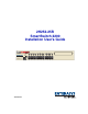
2H252-25R SmartSwitch 2200 Installation User’s Guide FAST ETHERNET WORKGROUP SWITCH LED MODE DPX-SPD 2H252-25R PWR CPU RESET 9034005-03 COM 2 1 4 3 2X RX-TX 6 5 4X 8 7 6X 10 9 8X 12 11 10X 16 15 14 13 12X 14X 22 21 20 19 18 17 16X 18X 20X 24 23 22X 24X
Only qualified personnel should perform installation procedures. NOTICE Enterasys Networks reserves the right to make changes in specifications and other information contained in this document and its web site without prior notice. The reader should in all cases consult Enterasys Networks to determine whether any such changes have been made. The hardware, firmware, or software described in this document is subject to change without notice.
FCC NOTICE This device complies with Part 15 of the FCC rules. Operation is subject to the following two conditions: (1) this device may not cause harmful interference, and (2) this device must accept any interference received, including interference that may cause undesired operation. NOTE: This equipment has been tested and found to comply with the limits for a class A digital device, pursuant to Part 15 of the FCC rules.
ENTERASYS NETWORKS, INC. PROGRAM LICENSE AGREEMENT BEFORE OPENING OR UTILIZING THE ENCLOSED PRODUCT, CAREFULLY READ THIS LICENSE AGREEMENT. This document is an agreement (“Agreement”) between You, the end user, and Enterasys Networks, Inc. (“Enterasys”) that sets forth your rights and obligations with respect to the Enterasys software program (“Program”) in the package. The Program may be contained in firmware, chips or other media.
5. UNITED STATES GOVERNMENT RESTRICTED RIGHTS. The enclosed Product (i) was developed solely at private expense; (ii) contains “restricted computer software” submitted with restricted rights in accordance with section 52.227-19 (a) through (d) of the Commercial Computer Software-Restricted Rights Clause and its successors, and (iii) in all respects is proprietary data belonging to Enterasys and/or its suppliers.
DECLARATION OF CONFORMITY Application of Council Directive(s): 89/336/EEC 73/23/EEC Manufacturer’s Name: Manufacturer’s Address: European Representative Address: Conformance to Directive(s)/Product Standards: Equipment Type/Environment: Enterasys Networks, Inc. 35 Industrial Way PO Box 5005 Rochester, NH 03866-5005 Enterasys Networks Ltd.
Contents Figures ............................................................................................................................................ix Tables.............................................................................................................................................. x ABOUT THIS GUIDE Using This Guide.............................................................................................................xi Structure of This Guide ...............................
3 INSTALLATION 3.1 3.2 3.3 3.4 3.5 4 TROUBLESHOOTING 4.1 4.2 4.3 A Using LANVIEW.............................................................................................. 4-1 Troubleshooting Checklist............................................................................... 4-6 Using the RESET Button................................................................................. 4-9 SPECIFICATIONS A.1 A.2 A.3 A.4 A.5 A.6 A.7 B Device Specifications ........................................
Figures Figure 1-1 3-1 3-2 3-3 3-4 3-5 3-6 3-7 4-1 4-2 B-1 B-2 B-3 B-4 B-5 Page The 2H252-25R SmartSwitch 2200................................................................................. 1-1 Tabletop or Shelf Installation ........................................................................................... 3-4 Attaching the Strain-Relief Bracket ................................................................................. 3-6 Attaching the Rackmount Brackets .................................
Tables Table 3-1 4-1 4-2 A-1 x Page Contents of 2H252-25R Carton ....................................................................................3-2 LANVIEW LEDs ............................................................................................................4-3 Troubleshooting Checklist.............................................................................................4-6 COM Port Pin Assignments .....................................................................................
About This Guide Welcome to the 2H252-25R SmartSwitch 2200 Installation User’s Guide. This guide describes the 2H252-25R SmartSwitch 2200 device and provides information concerning network requirements, installation, troubleshooting, and specifications. Important Notice Depending on the firmware version used in the 2H252-25R, some features described in this document may not be supported. Refer to the Release Notes shipped with the 2H252-25R to determine which features are supported.
Related Documents Appendix A, Specifications, contains information on functionality and operating specifications, connector pinouts, environmental requirements, and physical properties. Appendix B, Optional Installations and Mode Switch Bank Settings, describes how to remove the cover from the device, set the Mode Switch, and shows the location of an optional High Speed Interface Module (HSIM) or Very High Speed Interface Module (VHSIM) when one is installed.
Document Conventions DOCUMENT CONVENTIONS The guide uses the following conventions: NOTE: Calls the reader’s attention to any item of information that may be of special importance. TIP: Conveys helpful hints concerning procedures or actions. CAUTION: Contains information essential to avoid damage to the equipment. ELECTRICAL HAZARD: Warns against an action that could result in personal injury or death due to an electrical hazard.
1 Introduction This chapter introduces the 2H252-25R SmartSwitch 2200 device and provides information about how to obtain additional support from Enterasys Networks. Important Notice Depending on the firmware version used in the 2H252-25R, some features described in this document may not be supported. Refer to the Release Notes shipped with the 2H258-17R to determine which features are supported. 1.
Overview The 2H252-25R is used to connect individual high-bandwidth user devices, such as workstations, or to provide a central switching point for multiple 100-Mbps Fast Ethernet segments. The optional HSIMs provide high speed uplinks to networking technologies such as Fast Ethernet, Gigabit Ethernet, Fiber Distributed Data Interface (FDDI), Wide Area Network (WAN), and Asynchronous Transfer Mode (ATM). Some HSIMs can provide additional Fast Ethernet ports in varying media types.
Overview The RAD requests start at an interval of 1 per second. The interval then doubles after every transmission until an interval of 300 seconds is reached. At this point, the interval remains at 300 seconds. The RAD requests continue until an IP address is received from a RARP or BootP server, or an IP address is entered using Local Management. NOTE: The 2H252-25R will reboot after RAD is successful. 1.1.
Overview 1.1.5 Remote Monitoring (RMON) The 2H252-25R supports all nine Ethernet RMON groups. The Statistics, Alarms, Events and History groups are enabled on all ports by default. Enterasys Networks RMON Actions is a vendor-specific extension of RMON and provides the ability to set an “Action” on any SNMP MIB variable. The Action can be triggered by any RMON Event and/or Alarm. An example of an Action would be to turn off a MIB-2 interface if a broadcast threshold is crossed. 1.1.
Overview Administrators can configure up to four rate limit rules per port; however, each rule must not include conflicting 802.1p priority values. In order to control traffic inbound and outbound on the same port, two rate limit rules must be configured (one inbound and one outbound). Since the rate limiting operation occurs after the processing of the multi-layer classification rules, the two features can be combined to provide application-aware rate limiting.
Overview 1.1.11 802.1 Port Priority The 802.1 port priority is used to assign a default priority to the frames received without priority information in their tag header, map prioritized frames to the appropriate transmit queues, and prioritize frames according to protocol type. The 802.1 port priority is part of the IEEE 802.1D standard. 1.1.12 Management Management of the 2H252-25R is accomplished using SNMP compliant management tools for in-band Local Management.
Overview 1.1.15 Standards Compatibility The 2H252-25R is fully compliant with the IEEE 802.3, 802.3u, 802.3x, 802.1D, and 802.1Q standards. The 2H252-25R provides IEEE 802.1D Spanning Tree Algorithm (STA) support to enhance the overall reliability of the network and protect against “loop” conditions. The 2H252-25R supports a wide variety of industry standard MIBs including RFC 1213 (MIB II), RFC 1757 (RMON), RFC 1493 (Bridge MIB), RFC 1354 (FIB MIB), and RFC 1190 (Path MTU Discovery).
Getting Help 1.2 GETTING HELP For additional support related to the 2H252-25R or this document, contact Enterasys Networks using one of the following methods: World Wide Web http://www.enterasys.com/ Phone (603) 332-9400 Internet mail support@enterasys.com FTP ftp://ftp.enterasys.com Login anonymous Password your email address To send comments or suggestions concerning this document, contact the Technical Writing Department via the following email address: TechWriting@enterasys.
2 Network Requirements Before installing the 2H252-25R, review the requirements and specifications referred to in this chapter concerning the following: • SmartTrunk (Section 2.1) • 10BASE-T Twisted Pair Network (Section 2.2) • 100BASE-TX Twisted Pair Network (Section 2.3) The network installation must meet the requirements to ensure satisfactory performance of this equipment. Failure to do so will produce poor network performance.
100BASE-TX Network 2.3 100BASE-TX NETWORK The fixed ports (ports 1 through 24) of the 2H252-25R provide an RJ45 connection that supports Category 5 UTP cabling. The device at the other end of the twisted pair segment must meet IEEE 802.3u 100BASE-TX Fast Ethernet network requirements for the devices to operate at 100 Mbps. Refer to the Enterasys Networks Cabling Guide for details. NOTE: The fixed ports of the 2H252-25R support Category 5 UTP cabling that has an impedance between 85 and 111 ohms.
3 Installation ELECTRICAL HAZARD: Only qualified personnel should install the 2H252-25R. NOTE: Read the Release Notes shipped with the device to check for any exceptions to the supported features and operation documented in this guide. This chapter provides the instructions required to install the 2H252-25R. A Phillips screwdriver is required to install options into the device or install the device into a rack. Follow the order of the sections listed below to correctly install the device.
Installing Options Table 3-1 Contents of 2H252-25R Carton Item Quantity 2H252-25R 1 Antistatic Wrist Strap 1 Console Cable Kit 1 Rackmount Kit 1 Strain-Relief Bracket 1 Manual Accessory Kit 1 Power Cord 2 3. Remove the tape seal on the non-conductive bag to remove the 2H252-25R. 4. Perform a visual inspection of the device for any signs of physical damage, and contact Enterasys Networks if there are any signs of damage. Refer to Section 1.2 for details. 3.
Installing the Device 3.3 INSTALLING THE DEVICE The 2H252-25R may be installed on a tabletop, shelf, or in a 19-inch rack. Section 3.3.1 describes a tabletop or shelf installation and Section 3.3.2 describes the rackmount installation. ELECTRICAL HAZARD: To prevent possible personal injury and/or damage to the unit, do NOT connect power to the 2H252-25R until instructed to do so. 3.3.
Installing the Device Figure 3-1 Tabletop or Shelf Installation C B FAST ETHERNET WORKGROUP SWITCH 2 2X RX-TX A 6 5 4 3 1 LED MODE 4X 8 7 6X 12 11 10 9 8X 10X 16 15 14 13 12X 14X 22 21 20 19 18 17 16X 18X 20X 24 23 22X 24X DPX-SPD 2H252-25R PWR CPU RESET COM A = 15 cm (6 in) B = 57 cm (22.5 in) C = 53 cm (21 in) D = 213 cm (7 ft) D 4005_00_02 3.3.
Installing the Device CAUTION: To ensure proper ventilation and prevent overheating, leave a minimum clearance space of 5.1 cm (2.0 in) at the left, right, and rear of the 2H252-25R. WARNING: Before installing the 2H252-25R into a rack, ensure that the rack supports the device(s) without compromising the stability of the rack. Otherwise, personal injury and/or equipment damage may result.
Installing the Device Figure 3-2 Attaching the Strain-Relief Bracket Strain-Relief Bracket Screws Strain-Relief Bracket 2H252-25R COM PWR CPU RESET DPX-SPD 2X RX-TX LED MODE FAST ETHERNET WORKGROUP SWITCH 2 1 4X 4 3 6X 6 5 8X 8 7 10X 10 9 12X 12 11 14X 14 13 16X 16 15 18X 18 17 20X 20 19 22X 22 21 24X 24 23 4005_00_03 Rack Mounting the 2H252-25R Proceed as follows to install the 2H252-25R into a 19-inch rack: 1.
Installing the Device Figure 3-3 Attaching the Rackmount Brackets Rackmount Bracket Screws (Use only 6-32 x 1/4-inch flathead screws) Rackmount Bracket 2H252-25R COM PWR CPU RESET TELCO CONSOLE DPX-SPD 2X RX-TX LED MODE FAST ETHERNET WORKGROUP SWITCH 2 1 4X 4 3 6X 6 5 8X 8 7 10X 10 9 12X 12 11 14X 14 13 16X 18X 18 17 16 15 20X 20 19 22X 24X 24 23 22 21 4005-00-04 3.
Installing the Device 3.3.3 Connecting Power NOTE: The two power supplies in the 2H252-25R have automatic voltage sensing that allows connection to power sources ranging from 100–125 Vac, 2.5 A or 200–240 Vac, 1.25 A, 50/60 Hz. To connect the 2H252-25R to the power sources, proceed as follows: 1. Plug each power cord into a grounded wall outlet, see Figure 3-5. To take advantage of the load sharing and redundancy capabilities, each power cord must be plugged into a separate dedicated ac outlet.
Connecting to the Network 3.4 CONNECTING TO THE NETWORK This section provides the procedures for connecting unshielded twisted pair (UTP) and fiber optic segments from the network or other devices to the 2H252-25R. NOTE: If the 2H252-25R is being installed in a network using SmartTrunking, there are rules concerning the network cable and port configurations that must be followed for SmartTrunking to operate properly.
Connecting to the Network Figure 3-6 Connecting the Twisted Pair Segment Receive (RX) LED MODE LED MODE Switch in RXTX position RX-TX Transmit (TX) DPX-SPD P SWITCH 2 WORKGROU FAST ETHERNET 1 LED MODE 2X RX-TX 4X 6X 8X 10X 12X 14X 16X 18X 24 23 22 21 20 19 18 17 16 15 14 13 12 11 10 9 8 7 6 5 4 3 20X 24X 22X DPX-SPD PWR CPU RESET 2H252-25R COM LED MODE Switch Port Twisted Pair Cable 4005_00_07 3.
Connecting to the Network Figure 3-7 Schematic of Straight-Through and Crossover Cables Straight-Through Cable TO SmartSwitch RJ45 Port TO 10BASE-T or 100BASE-TX Device Port RX+ 1 1 RX+ RX 2 2 RX TX+ 3 3 TX+ TX 6 6 TX RJ45 to RJ45 NOTE: RX+/RX and TX+/TX must share a common color pair. Crossover Cable TO SmartSwitch RJ45 Port TO 10BASE-T or 100BASE-TX Device Port RX+ 1 1 RX+ RX 2 2 RX TX+ 3 3 TX+ TX 6 6 TX RJ45 to RJ45 25041-08 4.
Completing the Installation 3.5 COMPLETING THE INSTALLATION After installing the 2H252-25R and any optional HSIM or VHSIM, and making the connections to the network, proceed as follows: 1. Secure the cables by running the cables along the strain-relief bracket and tying them to the strain-relief bracket using cable ties. 2. The 2H252-25R is now ready to be configured through Local Management.
4 Troubleshooting This chapter provides information concerning the following: • Using LANVIEW (Section 4.1) • Troubleshooting Checklist (Section 4.2) • Using the RESET Button (Section 4.3) 4.1 USING LANVIEW The 2H252-25R uses Enterasys Networks’ built-in visual diagnostic and status monitoring system called LANVIEW. The LANVIEW LEDs (Figure 4-1) allow quick observation of the network status to aid in diagnosing network problems.
Using LANVIEW Figure 4-1 LANVIEW LEDs LED MODE RX-TX A Receive (RX) B DPX-SPD FAST ETHERNET WORKGROUP SWITCH LED MODE 2 1 6 5 4 3 4X 8 7 6X 12 11 10 9 8X Full Duplex Status DPX-SPD Transmit (TX) 2X RX-TX LED MODE RX-TX 10X 16 15 14 13 12X 14X Speed Status 16X 22 21 20 19 18 17 18X 20X 24 23 22X 24X DPX-SPD 2H252-25R PWR CPU RESET COM PWR CPU A LED functions when LED MODE switch is in the RX-TX position. This is the default switch setting.
Using LANVIEW Table 4-1 describes the LED indications and provides recommended actions as appropriate. Refer to the HSIM or VHSIM user’s guide for a description of the HSIM or VHSIM LED indications. NOTE: The terms flashing, blinking, and solid used in Table 4-1 indicate the following: Flashing indicates an LED is flashing randomly. Blinking indicates an LED is flashing at a steady rate (approximately 50% on, 50% off). Solid indicates a steady LED light. No pulsing.
Using LANVIEW Table 4-1 LANVIEW LEDs (Continued) LED Color State Recommended Action CPU Off Power off. Power up device. Red Blinking. Hardware failure has occurred. Contact Enterasys Networks for assistance. Solid. Resetting, normal power up reset. If the LED remains Red for several minutes, contact Enterasys Networks for assistance. Blinking. Crippled. Contact Enterasys Networks for assistance. Solid. Testing.
Using LANVIEW Table 4-1 LANVIEW LEDs (Continued) LED Color State Recommended Action TX (Transmit) Off Port enabled, and no activity. 1. Ensure that the STA is enabled and that there is a valid link. 2. Contact Enterasys Networks for assistance. Should flash green every two seconds indicating BPDUs being sent if STA is enabled and there is a valid link. Green Flashing. Indicates activity. Rate indicates data rate. None. Amber Blinking. Port in standby. 1. Ensure that the port is not disabled.
Troubleshooting Checklist 4.2 TROUBLESHOOTING CHECKLIST If the 2H252-25R is not working properly, refer to Table 4-2 for a checklist of possible problems, causes, and recommended actions to resolve the problem. Table 4-2 Troubleshooting Checklist Problem Possible Cause Recommended Action All LEDs are OFF. Loss of power. Check for proper connection of the power cable and its access to a live outlet. Installed improperly.
Troubleshooting Checklist Table 4-2 Troubleshooting Checklist (Continued) Problem Possible Cause Recommended Action Cannot navigate beyond Password screen. Improper Community Names Table. 1. Refer to the SmartSwitch Series 2E253, 2H252, 2H253 and 2H258 Local Management User’s Guide for Community Names Table setup. 2. If you have forgotten the Community Names, refer to Appendix B for instructions on how to set the mode switch to reset the Community Names to their default values.
Troubleshooting Checklist Table 4-2 Troubleshooting Checklist (Continued) Problem Possible Cause Recommended Action Port(s) goes into standby for no apparent reason. Loop condition detected. 1. Verify that Spanning Tree is enabled. Refer to the SmartSwitch Series 2E253, 2H252, 2H253 and 2H258 Local Management User’s Guide for the instructions to set the type of STA. 2. Review network design and delete unnecessary loops. 3. If the problem continues, contact Enterasys Networks for assistance.
Using the RESET Button 4.3 USING THE RESET BUTTON The RESET button shown in Figure 4-2 resets and re-initializes the 2H252-25R. CAUTION: Pressing the RESET button resets the device, and all current switching being performed by the device is halted. A network downtime of up to two minutes will result from this action.
A Specifications This appendix provides operating specifications for the Enterasys Networks 2H252-25R. Enterasys Networks reserves the right to change these specifications at any time without notice. A.1 DEVICE SPECIFICATIONS Processors: Intel i960 RISC processor Power PC Dynamic Random Access Memory (DRAM): 20 MB expandable to 32 MB FLASH Memory: 8 MB Shared Memory: 4 MB A.2 PHYSICAL PROPERTIES Dimensions: 7.11H x 43.18W x 46.99D (cm) 2.8H x 17W x 18.5D (in) Approximate Weight (Unit): 8.
Electrical Specifications A.3 ELECTRICAL SPECIFICATIONS Line Input Range, Volts (V) 100–125 Vac 200–240 Vac Input Current, Amperes (A) 2.3 A 1.2 A Frequency, Hertz (Hz) 50/60 Hz 50/60 Hz Input Power, Volt Amperes (VA) 250 VA 250 VA A.4 ENVIRONMENTAL REQUIREMENTS Operating Temperature: 5°C to 40°C (41°F to 104°F) Storage Temperature: -30°C to 73°C (-22°F to 164°F) Operating Relative Humidity: 5% to 90% (non-condensing) A.
COM Port Pinout Assignments A.6 COM PORT PINOUT ASSIGNMENTS The COM port is a serial communications port that supports Local Management or connection to a UPS. Table A-1 shows the COM port pin assignments.
B Optional Installations and Mode Switch Bank Settings ELECTRICAL HAZARD: ONLY QUALIFIED SERVICE PERSONNEL SHOULD ATTEMPT THE FOLLOWING PROCEDURES. NUR QUALIFIEZIERTE SERVICE PERSONNAL DIE FOLGENDE PROCEDURE FOLGEN SOLLTEN. SOLAMENTE PERSONAL CALIFICADO DEBE INTENTAR ESTE PROCEDIMIENTO.
Removing the Chassis Cover B.2 REMOVING THE CHASSIS COVER This section describes how to remove the 2H252-25R chassis cover. DO NOT REMOVE THE COVER FROM THE 2H252-25R WHILE POWER IS APPLIED TO THE UNIT. HAZARDOUS VOLTAGES ARE PRESENT AND COULD CAUSE PERSONAL INJURY AND/OR DAMAGE THE UNIT. DO NOT POWER UP THE 2H252-25R AGAIN UNTIL THE COVER AND SCREWS ARE IN PLACE. DECKEL VON DAS 2H252-25R NICHT ABZIEHEN UNTER SPANNUNG. GEFAHR FÜR DAS PERSONNAL UND/ODER DAS GERÄT WEGEN GEFÄHRLICHE SPANNUNGEN ENSTEHT.
Removing the Chassis Cover To remove the chassis cover, proceed as follows: 1. Disconnect the 2H252-25R from the network as follows: a. Unplug both power cords from the rear of the chassis. ELECTRICAL HAZARD: TURN OFF THE 2H252-25R BY UNPLUGGING THE POWER CORD FROM THE REAR OF THE CHASSIS. AM HINTEN DES 2H252-25R STECHEI ABZIEHEN UM AUS ZU SCHALTEN. APAGUE EL 2H252-25R DESENCHUFE EL CABLE DE LA UNIDAD.
Removing the Chassis Cover 3. Use a Phillips screwdriver to remove the four screws attaching the cover to the chassis. (See Figure B-1.) Figure B-1 Removing the Chassis Cover Screws (4) Chassis Cover Front Panel Chassis Note: If the device was rack mounted, the four screws fastening the cover to the front panel are removed and installed along with the rackmount brackets. 2504-30 4.
Setting the Mode Switches B.3 SETTING THE MODE SWITCHES Figure B-2 shows the location of the mode switches and the switch settings for normal operation. These switches are set at the factory and rarely need to be changed. Switch definitions and positions are as follows: • Switches 1 through 4 – For Enterasys Networks use only. • Switch 5 – COM Port Autobaud. The default (OFF) position enables Autobaud sensing on the COM port for Local Management sessions.
Setting the Mode Switches • Switch 6 – Forced BootP. NOTE: After changing the position of switch 6, DO NOT reapply power to the chassis until there is a station on the network acting as a BootP server, which contains the downloadable firmware image file. DO NOT attempt a Forced BootP unless a BootP server has been configured for the 2H252-25R. The BootP server references the location of a station acting as a Trivial File Transfer Protocol (TFTP) server containing the 2H252-25R image file.
SIMM Upgrade B.4 SIMM UPGRADE Memory upgrade is available for the 2H252-25R to expand its DRAM to 32 MB. This section explains how to locate and add/replace a Single In-line Memory Module (SIMM). For information on the available SIMM upgrades, call Enterasys Networks for technical support. For details on getting help, refer to Section 1.2. B.4.1 Locating SIMMs Figure B-3 shows the two locations of the DRAM SIMM connector.
SIMM Upgrade B.4.2 Installing the DRAM SIMM CAUTION: Observe all antistatic precautions when handling sensitive electronic equipment. To install a DRAM SIMM, refer to Figure B-4 and proceed as follows: 1. With the SIMM alignment notch oriented as shown in Figure B-4, insert the SIMM down between the connector teeth. 2. Pivot the SIMM downward so the connector clips align with the two side notches of the SIMM and the connector clips lock the SIMM into place.
Installing Optional HSIM or VHSIM Interface Modules B.5 INSTALLING OPTIONAL HSIM OR VHSIM INTERFACE MODULES Figure B-5 shows the location of the two connectors for an optional High HSIM or VHSIM. Depending on the HSIM or VHSIM installed, one or both connectors are used. NOTE: The installation instructions for the optional HSIM or VHSIM are in the associated user’s guide.
Index Numerics F 100BASE-T requirements 2-2 10BASE-T requirements 2-1 2H252-25R description of 1-1 front panel 1-1 802.
M S Management use of 1-6 Memory upgrading B-7 Mode Switch setting B-5 SIMMs installing DRAM B-8 location B-7 SmartTrunk introduction to 1-3 Specifications A-1 Standards compatibility 1-7 Switching options introduction to 1-6 N Network connection of twisted pair cables 3-9 Network connections 3-9 T P Troubleshooting 4-1 checklist 4-6 Twisted pair cables connection of 3-9 Physical properties A-1 Port redirect function introduction to 1-4 Power connection 3-8 U Unpacking 3-1 R Redirect functions por