
Install Guide
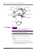
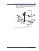
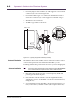
Table Of Contents

Ensemble Communications Inc.
4-8
Operator’s Guide to the Fiberless System
IF Cable Installation
Caution
If the base station has been powered up, power it off before
connecting or disconnecting the RG-6 cable at either end
because the cable may have –48 VDC across the connector.
1. Run RG-6 coaxial cable between the base station and the ODU.
The maximum permissible individual cable run length is 1,000
feet (300 meters). Ensure there is an 18-inch (45 cm) service
loop at each end of the cable.
When required, encase cables in plastic or metal conduit or
cable duct, maintaining a minimum bend radius of two inches.
Note Depending on local codes and the HVAC design of a particular building,
plenum-rated cable may be required.
Normally, cables between the ODU and the indoor base station
equipment should not be spliced. However, if a cable splice
cannot be avoided, use only approved connectors.
2. Label each end of the cable individually with numbers or col-
ors using a cable labeling tape such as is available from 3M.
Cable Terminations The RG-6-type coaxial cable uses a male TNC connector to connect
to the ODU. Follow the instructions from the connector
manufacturer to prepare the cable and install the connector. Use
only the recommended crimping tool. (See page 3-10 for the
recommended tool.)
1. Install the TNC connector on the IF cable.
2. Connect the cable to the lightning suppressor.
3. Make an 18-inch (45 cm) IF jumper cable with a TNC connector
on each end.
4. Install the 18-inch IF jumper cable between the ODU and the
lightning suppressor.
5. Waterproof the connector using a sealing type of heat shrink-
able tubing, cold shrink tubing, or 3M type 66 vinyl tape with a
coating of 3M electrical coating.
Note Waterproofing is not required for connectors terminating inside.
6. At the base station, install a TNC connector on each IF cable.
See page 5-7 for connections at the base station indoor equipment.