
User's Manual

Ensemble Communications Inc.
6-10
Operator’s Guide to the Fiberless System
WARNING
The cable may have -48 VDC across the connector when
connected to the CPE. Therefore, DO NOT apply power to
the CPE before connecting or disconnecting the RG-6
cable at either end.
Note The CPE requires a nominal of 110/220 VAC, 10 Amps. Each CPE
requires a separate circuit breaker. UPS is optional.
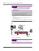
• Connect the RG-6 cable to the CPE ODU1 port connector (see
Figure 6-6).
• Plug the CPE power cord into a 110 VAC power outlet as
shown in the Figure 6-6.
• Turn on breaker to the CPE and verify that the fan is operating.
Note The CPE has a field-replaceable 3-Amp fuse located behind the switch
housing. Remove the housing to replace this fuse.
Figure 6-6. Power Cable Installation
Caution
If you power off the CPE, wait five seconds before turning on
the power again.
SIC
RG-6 Cable
Power Cable
CPE ODU
(rear view)
TNC IF Port
PC