
User's Manual

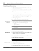


Table Of Contents

Ensemble Communications Inc.
CPE Site Setup
6-9
5. Waterproof the connector using a sealing type of heat shrink-
able tubing, cold shrink tubing, or 3M type 66 vinyl tape with a
coating of 3M electrical coating.
Note Waterproofing is not required for connectors that terminate inside.
6. At the CPE indoor equipment, install a TNC connector on each
IF cable.
7. Following the system design plan, connect the cable from each
antenna unit to a specific ODU connector on the CPE.
CPE Indoor Installation
Indoor Equipment
Placement
The Fiberless 320 CPE can be located in a wiring closet with other
communications equipment or in a customer suite. Its compact
low-profile package, rubber feet, and optional mounting brackets
make it easy to mount it in either a standard 19-inch (47 cm) or 23-
inch (57 cm) cabinet or stack on a shelf using the included rack-
mounted ears (see Figure 6-6).
Figure 6-6. CPE Showing Airflow Vents and Rack-mounted Ears
Caution
When placing the CPE, do not block the airflow vents that are
located on both sides of the unit.
CPE Indoor Access
Requirement
Allow enough room to accommodate the size of the unit (1.5 U [2.6
inches/6.6 cm) by 9.5 inches (25 cm) deep) with enough clearance
to accommodate termination of up to 16 data cables or 12 T1
cables, two cables to the ODU, and a power cord.
DO NOT BLOCK
AIRFLOW VENTS
Rack-Mount Ears
Do not block airflow vents
located on both sides