
User's Manual


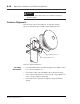


Table Of Contents

Ensemble Communications Inc.
6-14
Operator’s Guide to the Fiberless System
2. Note the peak voltage variances, and sweep the antenna in the
other direction.
Main Lobe Location 3. Move the antenna to the strongest signal reference of the two.
4. Repeat steps 1-3 for the vertical alignment.
Antenna Alignment
Completion
5. When alignment is completed, disconnect the BNC cable at
both the ODU BNC connector and the DVM.
6. Recap the ODU BNC connector and stow all tools.
CPE Software Configuration
See page 7-65.
CPE Subscriber Interface Cards (SICs)
Customer equipment is connected to the SIC ports at the rear of the
CPE. Slot 1 may be the four-port T1, and slot 3 may be the six-port
10/100BaseT.
Note Release 1.0 does not support slot 2.
Connect CPE SIC ports to the customer equipment.
CPE LEDs
Within 45 seconds of successful registration, the CPE establishes an
active data connection.
The CPE Status, ODU, and Sync LEDs, as shown in Figure 9-1, will
display solid green if the CPE is functioning properly.
Note At power up, Status, ODU, and Sync LEDs are red.
See “Troubleshooting” on page 9-1 for the LED descriptions.