
User's Manual


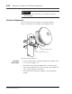


Table Of Contents

Ensemble Communications Inc.
CPE Site Setup
6-13
Figure 6-9. Digital Voltage Multimeter (DVM) Connection
Note The alignment port is factory configured to provide a voltage of 0 - 5
VDC. Any received signal level (RSL) of less than 0.5 VDC is translated
as 0 and the readout displays a blinking 0.
Receive Signal Levels
for Various Voltages
Note These values are a guide. They will be affected by rain fading, antenna
alignment accuracy, and antenna tilt angle.
Voltage Readings 1. Using the 7/16-inch socket wrench set, start sweeping the
antenna slowly to one direction. Pause every two turns, wait-
ing for the readout to stabilize before preceding.
CPE ODU
(rear view)
Digital
Voltage
Multimeter
BNC Alignment
Connector
Table 6-1: RSL and Voltages
Rx pwr (dBm) RSL (V)
-75 1.08
-70 1.39
-65 1.71
-60 2.04
-55 2.35
-50 2.69
-45 3.00
-40 3.33
-35 3.65
-30 3.96
-25 4.29
-20 4.61