
User's Manual


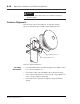


Table Of Contents

Ensemble Communications Inc.
CPE Site Setup
6-11
CPE Indoor Procedure • Select an environment that is dirt and dust free for the CPE.
• Situate the CPE box in a rack, shelf mount or on a table top.
Connect the power cable to the power connector on the back of
the CPE indoor equipment.
WARNING
The cable may have -48 VDC across the connector when
connected to the CPE. Therefore, DO NOT apply power to
the CPE before connecting or disconnecting the RG-6
cable at either end.
Note The CPE requires a nominal of 110/220 VAC, 10 Amps. Each CPE
requires a separate circuit breaker. UPS is optional.
• Connect the RG-6 cable to the CPE ODU1 port connector (see
Figure 6-7).
• Plug the CPE power cord into either a 110/220 VAC power out-
let (Figure 6-7 shows a typical 110 VAC outlet).
• Turn on breaker to the CPE and verify that the fan is operating.
Note The CPE has a field-replaceable 3-Amp fuse located behind the switch
housing. Remove the housing to replace this fuse.
Figure 6-7. Power Cable Installation
SIC
RG-6 Cable
Power Cable
CPE ODU
(rear view)
TNC IF Port
Laptop
10BaseT