AI DIGITAL VIDEO RECORDER Quick Start Guide V1.0.
Foreword Welcome Thank you for purchasing our Digital Video Recorder (DVR). This Quick Start Guide (hereinafter referred to be "the Guide") will help you become familiar with our DVR in a short time. Please read the Guide carefully before starting using your DVR and properly keep it for future reference. Important Safeguards and Warnings Operation Requirement Do not place or install the Device in a place exposed to sunlight or near the heat source. Keep the Device away from dampness, dust or soot.
Signal Words Meaning Indicates a potential risk which, if not avoided, could result in property CAUTION damage, data loss, lower performance, or unpredictable result. Provides additional information as the emphasis and supplement to the NOTE text. Privacy Protection Notice As the device user or data controller, you might collect personal data of others such as face, fingerprints, car plate number, Email address, phone number, GPS and so on.
Table of Contents Foreword .................................................................................................................................................... I 1 Quick Start ............................................................................................................................................. 1 1.1 Unpacking the Accessories ........................................................................................................... 1 1.2 Checking the Components.........
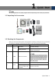
1 Quick Start The actual appearance or quantity might be different depending on the model you purchased. 1.1 Unpacking the Accessories 1.2 Checking the Components When you receive the DVR, please check against the following checking list. If any of the items are missing or damaged, contact the local retailer or after-sales engineer immediately. Sequence 1 Checking items Requirement Appearance No obvious damage. Packing materials No broken or distorted positions that could be caused by hit.
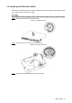
1.3 Installing Hard Disk Drive (HDD) Please check whether the HDD is already installed for the first use. Please use enterprise HDD or surveillance HDD instead of PC HDD. Shut down the DVR and unplug the power cable before opening the cover to replace the HDD. Step 1 Remove the screws to take off the cover. Figure 1-1 Taking off cover Step 2 Put two screws on the HDD and twist one turn. Figure 1-2 Putting in screws Step 3 Align the two screws with the holes on the device.
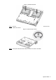
Figure 1-3 HDD placement Step 4 Turn the device and put in the other two screws, and then fasten all screws to fix the HDD to the device. Figure 1-4 HDD fixing to device Step 5 Use power cable and data cable to connect the device and HDD.
Figure 1-5 Cables connection Step 6 Put back the cover and fasten the screws. Figure 1-6 Installation completed 1.4 Booting up Ensure the input voltage corresponds to the power requirement of the DVR. Turn on the DVR after the power cable is properly connected. To protect the DVR, connect the DVR with the power cable first, and then connect to the power source.
On the connected display, the live view screen is displayed. If you turn on the DVR during the time period that is configured for recording, the system starts recording after it is turned on, and you will see the icon indicating recording status in specific channels.
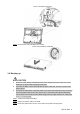
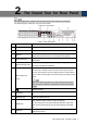
2 The Grand Tour for Rear Panel The actual appearance might be different depending on the model you purchased. The following figure shows the rear panel of the DVR. Figure 2-1 Rear panel Table 2-1 Port description No. Port Name Function 1 Video input port Connects to analog camera to input video signal. 2 Audio output port Outputs audio signal to the devices such as the sound box.
No. Port Name Function 11 Power input port Inputs power. 12 Alarm output port 1– 5 (NO1–NO5; C1–C5; NC5) 13 14 Power button 5 groups of alarm output ports (Group 1: port NO1– C1,Group 2:port NO2–C2,Group 3:port NO3–C3, Group 4: port NO4–C4, Group 5: port NO5, C5, NC5). These ports output alarm signal to the alarm device. Please make sure power supply to the external alarm device. NO: Normal open alarm output port. C: Alarm output public end. NC: Normal close alarm output port.
3 Local Configurations Please read the following notes prior to using your DVR. The interfaces in the Guide are used for introducing the operations and only for reference. The actual product shall govern. For details about operations of the DVR, see User’s Manual. To enter the Main Menu, right-click on the live view screen to display the shortcut menu, and then click Main Menu and login the system. 3.
Figure 3-2 Password protection Table 3-1 Password protection mode description Password Protection Mode Description Email Address Enter the reserved email address. In the Email Address box, enter an email address for password reset. In case you forgot password, enter the security code that you will get from this reserved email address to reset the password of admin. Security Questions Configure the security questions and answers.
Not all models are provided with reset button. Step 1 Enter the login interface. If you have configured unlock pattern, the unlock pattern login interface is displayed. Click Forgot Pattern, the password login interface is displayed. See Figure 3-3. If you did not configure unlock pattern, the password login interface is displayed. See Figure 3-3. Figure 3-3 System login Step 2 Click . If you did not set the reserved email address, the email entering interface is displayed.
After clicking OK, the system will collect your information for password reset, and the information includes but not limited to email address, MAC address, and device serial number. Please read the prompt carefully before clicking OK. Figure 3-5 Reset password Step 4 Reset the password. QR code Scan the QR code on the actual interface, and then follow the onscreen instructions to get the security code in your reserved email address. In the Security code box, enter the security code.
Figure 3-6 Security questions Step 5 Click Next and then follow the onscreen instructions to complete the password resetting. 3.3 Adding Remote Device You can add remote devices by adding the IP address. This function is available after having configured the channel type as IP channel by selecting Main Menu > CAMERA > CHANNEL TYPE. Step 1 Select Main Menu > CAMERA > REGISTRATION > Registration. The Registration interface is displayed. Step 2 Click IP Search. The searched devices are displayed.
Figure 3-7 Added device 3.4 Configuring Recording Storage Schedule Select Main Menu > STORAGE > SCHEDULE > Record, the Record interface is displayed, see Figure 3-8. The default setting is 24 hours recording for all channels. You can modify the settings if needed.
Figure 3-8 Record storage configuration 3.5 Playing Back Recorded Video You can search for and play back the recorded videos saved on the DVR. Step 1 Select Main Menu > VIDEO. The video search interface is displayed. See Figure 3-9.
Figure 3-9 Recorded video Step 2 Select the source as From R/W HDD or From I/O Device from where you want to search for the recorded video. Step 3 In the search type list, select RECORD. Step 4 In the calendar area, select a date. Step 5 In the CAM NAME list, select a channel. Step 6 Click . The system starts playing recorded video. 3.6 Configuring P2P Settings You can add the DVR into your cell phone client or the platform to manage. For details, please refer to the P2P operation manual.
Figure 3-10 P2P interface Step 2 Enable the P2P function. Step 3 Click Apply. You can start adding the DVR into Cell Phone Client or the platform. 3.6.2 Adding DVR into Cell Phone Client To use P2P function, take adding device into Cell Phone Client as an example. You can also enter the QR code interface by clicking on the top right of the interfaces after you have entered the Main Menu. Step 1 Use your cell phone to scan the QR code under Cell Phone Client to download the application.
Figure 3-11 Add device Step 4 Tap P2P, enter a name for the DVR, the username and password, scan the QR code under Device SN, and then tap Start Live Preview. The DVR is added and displayed on the live view interface of the cell phone. See Figure 3-12.
3.7 Logout On the top right of the Main Menu interface or any interface after you have entered the Main Menu, click . Select Logout, you will log out the DVR. Select Reboot, the DVR will be rebooted. Select Shutdown, the DVR will be turned off. You can also press the power button on the DVR to turn it off.
4 Web Login Open the browser, enter the IP address of the DVR, and then press Enter. The Login in dialog box is displayed. See Figure 4-1. Properly enter the user name and password to login the web. For details, see User’s Manual. Figure 4-1 Login Device initialization is required at the first login. The default administrator account is admin. The password is the one that was configured during initializing settings.