
User Manual
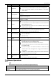
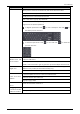
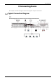
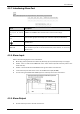
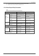
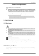
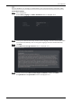
Table Of Contents
- Regulatory Information
- Foreword
- Important Safeguards and Warnings
- 1 Introduction
- 2 Getting Started
- 2.1 Checking the Components
- 2.2 Installing HDD
- 2.2.1 DH-XVR8216A-4KL-I/DH-XVR8208A-4K-I/DH-XVR8208A-4KL–I/DH-XVR7208A-4KL-I/DH-XVR7216A-4KL-I/DH-XVR52xxAN-I2/DH-XVR52xxA-I2/DH-XVR52xxAN-4KL-I2/DH-XVR52xxA-4KL-I2/DH-XVR72xxA-4K-I2/DH-XVR7216AN-4K-I2/DH-XVR4216AN-I
- 2.2.2 DH-XVR8816S-4KL-I/DH-XVR5808S-I2/DH-XVR5816S-I2/DH-XVR5832S-I2/DH-XVR5816S-4KL-I2/DH-XVR5832S-4KL-I2/DH-XVR7808S-4K-I2/DH-XVR7816S-4K-I2/DH-XVR5816S-4KL-I2-LP/DH-XVR7816S-4KL-X-LP-V2
- 2.2.3 DH-XVR5408L-I2/DH-XVR5416L-I2/DH-XVR5432L-I2/DH-XVR5416L-4KL-I2/DH-XVR5432L-4KL-I2/DH-XVR7408L-4K-I2/DH-XVR7416L-4K-I2
- 2.2.4 DH-XVR5104H-I/DH-XVR5108H-I/DH-XVR5116H-I/DH-XVR7104HE-4KL-I/DH-XVR7108HE-4KL-I/DH-XVR7116HE-4KL-I/DH-XVR51xxHS-I2/DH-XVR51xxH-I2/DH-XVR51xxHE-I2/DH-XVR51xxHS-4KL-I2/DH-XVR51xxH-4KL-I2/DH-XVR51xxHE-4KL-I2/DH-XVR71xxH-4K-I2/DH-XVR71xxHE-4K-I2/DH-...
- 2.2.5 DH-XVR5104C-I3/DH-XVR5108C-I3/DH-XVR5104C-4KL-I3
- 3 The Grand Tour
- 3.1 Front Panel
- 3.1.1 DH-XVR5104H-I/DH-XVR5108H-I/DH-XVR5116H-I
- 3.1.2 DH-XVR7104HE-4KL-I/DH-XVR7108HE-4KL-I/DH-XVR7116HE-4KL-I/DH-XVR71xxH-4K-I2/DH-XVR71xxHE-4K-I2
- 3.1.3 DH-XVR7208A-4KL-I/DH-XVR7216A-4KL-I/DH-XVR7216AN-4K-I2
- 3.1.4 DH-XVR8216A-4KL-I/DH-XVR8208A-4K-I/DH-XVR8208A-4KL–I
- 3.1.5 DH-XVR51xxHS-I2/DH-XVR51xxH-I2/DH-XVR51xxHE-I2/DH-XVR52xxAN-I2/DH-XVR52xxA-I2/DH-XVR51xxHS-4KL-I2/DH-XVR51xxH-4KL-I2/DH-XVR51xxHE-4KL-I2/DH-XVR52xxAN-4KL-I2/DH-XVR52xxA-4KL-I2/DH-XVR5104HS-I3/DH-XVR5104H-I3/DH-XVR5104HE-I3/DH-XVR5108HS-I3/DH-XVR...
- 3.1.6 DH-XVR8816S-4KL-I/DH-XVR7808S-4K-I2/DH-XVR7816S-4K-I2/DH-XVR7816S-4KL-X-LP-V2
- 3.1.7 DH-XVR7408L-4K-I2/DH-XVR7416L-4K-I2
- 3.1.8 DH-XVR5408L-I2/DH-XVR5416L-I2/DH-XVR5432L-I2/DH-XVR5416L-4KL-I2/DH-XVR5432L-4KL-I2
- 3.1.9 DH-XVR5808S-I2/DH-XVR5816S-I2/DH-XVR5832S-I2/DH-XVR5816S-4KL-I2/DH-XVR5832S-4KL-I2/DH-XVR5816S-4KL-I2-LP
- 3.1.10 DH-XVR1B08-I/DH-XVR1B08H-I/DH-XVR1B16-I/DH-XVR1B04-I/DH-XVR1B04H-I
- 3.1.11 DH-XVR5104C-I3/DH-XVR5108C-I3/DH-XVR5104C-4KL -I3
- 3.2 Rear Panel
- 3.2.1 DH-XVR5104H-I/DH-XVR5108H-I/DH-XVR5116H-I/DH-XVR7104HE-4KL-I/DH-XVR7108HE-4KL-I/DH-XVR7116HE-4KL-I/DH-XVR51xxH-I2/DH-XVR51xxHE-I2/DH-XVR51xxH-4KL-I2/DH-XVR51xxHE-4KL-I2//DH-XVR71xxH-4K-I2/DH-XVR71xxHE-4K-I2/DH-XVR5104H-I3/DH-XVR5104HE-I3/H-XVR51...
- 3.2.2 DH-XVR51xxHS-I2/DH-XVR51xxHS-4KL-I2/DH-XVR5104HS-I3/DH-XVR5108HS-I3/DH-XVR5104HS-4KL-I3/DH-XVR4104HS-I/DH-XVR4108HS-I/DH-XVR4104C-I/DH-XVR4108C-I/DH-XVR4116HS-I
- 3.2.3 DH-XVR7208A-4KL-I/DH-XVR7216A-4KL-I/DH-XVR52xxAN-I2/DH-XVR52xxA-I2/DH-XVR52xxAN-4KL-I2/DH-XVR-52xxA-4KL-I2/DH-XVR72xxA-4K-I2/DH-XVR7216AN-4K-I2/DH-XVR4216AN-I
- 3.2.4 DH-XVR8216A-4KL-I/DH-XVR8208A-4K-I/DH-XVR8208A-4KL–I
- 3.2.5 DH-XVR8816S-4KL-I/DH-XVR58xxS-I2/DH-XVR58xxS-4KL-I2/DH-XVR78xxS-4K-I2
- 3.2.6 DH-XVR5816S-4KL-I2-LP/DH-XVR7816S-4KL-X-LP-V2
- 3.2.7 DH-XVR5408L-I2/DH-XVR5416L-I2/DH-XVR5432L-I2/DH-XVR5416L-4KL-I2/DH-XVR5432L-4KL-I2/DH-XVR7408L-4K-I2/DH-XVR7416L-4K-I2
- 3.2.8 DH-XVR1B16-I/DH-XVR1B08-I/DH-XVR1B08H-I/DH-XVR1B04-I/DH-XVR1B04H-I
- 3.2.9 DH-XVR5104C-I3/DH-XVR5108C-I3/DH-XVR5104C-4KL -I3
- 3.3 Remote Control Operations
- 3.4 Mouse Operations
- 3.1 Front Panel
- 4 Connecting Basics
- 5 Local Configurations
- 5.1 Initial Settings
- 5.1.1 Booting up
- 5.1.2 Initializing the Device
- 5.1.3 Resetting Password
- 5.1.4 Setting Up with the Startup Wizard
- 5.1.4.1 Entering Startup Wizard
- 5.1.4.2 Configuring General Settings
- 5.1.4.3 Configuring Date and Time Settings
- 5.1.4.4 Configuring Network Settings
- 5.1.4.5 Configuring P2P Settings
- 5.1.4.6 Configuring Encode Settings
- 5.1.4.7 Configuring Snapshot Settings
- 5.1.4.8 Configuring Basic Storage Settings
- 5.1.4.9 Configuring Recorded Video Storage Schedule
- 5.1.4.10 Configuring Snapshot Storage Schedule
- 5.2 Live View
- 5.2.1 Live View Screen
- 5.2.2 Live View Control bar
- 5.2.2.1 Instant Playback
- 5.2.2.2 Digital Zoom
- 5.2.2.3 Instant Record
- 5.2.2.4 Manual Snapshot
- 5.2.2.5 Mute (Analog channel only)
- 5.2.2.6 White Light (Supported on camera with white light function)
- 5.2.2.7 Siren (Supported on camera with siren function)
- 5.2.2.8 Two-way Talk (Digital channel only)
- 5.2.2.9 Adding Camera (Digital channel only)
- 5.2.3 Navigation Bar
- 5.2.4 Shortcut Menu
- 5.2.5 AI Preview Mode
- 5.2.6 Channel Sequence
- 5.2.7 Color Setting
- 5.2.8 Live View Display
- 5.2.9 Configuring Tour Settings
- 5.2.10 Quick Operation Bar
- 5.3 Entering Main Menu
- 5.4 Controlling PTZ Cameras
- 5.5 Configuring Camera Settings
- 5.6 Configuring Remote Devices
- 5.7 Configuring Record Settings
- 5.8 Configuring Snapshot Settings
- 5.9 Playing Back Video
- 5.10 Alarm Events Settings
- 5.11 AI Function
- 5.11.1 For Pro AI Series
- 5.11.2 For Lite AI Series
- 5.12 IoT Function
- 5.12.1 Configuring Sensor Settings
- 5.12.2 Configuring Temperature and Humidity Camera
- 5.12.3 Configuring Wireless Siren
- 5.13 Configuring POS Settings
- 5.14 Configuring Backup Settings
- 5.15 Network Management
- 5.15.1 Configuring Network Settings
- 5.15.1.1 Configuring TCP/IP Settings
- 5.15.1.2 Configuring Port Settings
- 5.15.1.3 Configuring Wi-Fi Connection Settings
- 5.15.1.4 Configuring 3G/4G Settings
- 5.15.1.5 Configuring PPPoE Settings
- 5.15.1.6 Configuring DDNS Settings
- 5.15.1.7 Configuring EMAIL Settings
- 5.15.1.8 Configuring UPnP Settings
- 5.15.1.9 Configuring SNMP Settings
- 5.15.1.10 Configuring Multicast Settings
- 5.15.1.11 Configuring Register Settings
- 5.15.1.12 Configuring Alarm Center Settings
- 5.15.1.13 Configuring P2P Settings
- 5.15.2 Configuring Network Testing Settings
- 5.15.1 Configuring Network Settings
- 5.16 Configuring Account Settings
- 5.17 Audio Management
- 5.18 Storage Management
- 5.18.1 Configuring Basic Settings
- 5.18.2 Configuring the Recording and Snapshot Schedule
- 5.18.3 Configuring Disk Manager
- 5.18.4 Configuring Record
- 5.18.5 Configuring Advance Settings
- 5.18.6 Configuring Disk Quota
- 5.18.7 Configuring HDD Detecting Settings
- 5.18.8 Configuring Record Estimate
- 5.18.9 Configuring FTP Storage Settings
- 5.19 Security Center
- 5.20 Configuring System Settings
- 5.21 Viewing Information
- 5.22 Logout the Device
- 5.1 Initial Settings
- 6 Web Operations
- 7 FAQ
- Appendix 1 Glossary
- Appendix 2 HDD Capacity Calculation
- Appendix 3 Compatible Backup Devices
- Appendix 4 Compatible CD/DVD Burner List
- Appendix 5 Compatible Displayer List
- Appendix 6 Compatible Switcher
- Appendix 7 Earthing
- Appendix 8 RJ45-RS-232 Connection Cable Definition
- Appendix 9 Cybersecurity Recommendations

User’s Manual
37
4.3.1 Introducing Alarm Port
The alarm input ports are dependent on the model you purchased.
Icon Description
1, 2, 3, 4, 5, 6, 7, 8, 9,
10, 11, 12, 13, 14, 15,
16
ALARM 1 to ALARM 16. The alarm becomes active in low voltage.
NO1 C1, NO2 C2, NO3
C3
There are four groups of normally open activation output (on/off button).
Ground cable.
485 A/B
485 communication port. They are used to control devices such as decoder.
120Ω should be parallel connected between A, B lines if there are too many
PTZ decoders.
4.3.2 Alarm Input
Refer to the following figure for more information.
Grounding alarm inputs which includes NO (Normally Open) and NC (Normally Closed) type.
Parallel connect COM end and GND end of the alarm detector (Provide external power to the
alarm detector).
Parallel connect the Ground of the DVR and the ground of the alarm detector.
Connect the NC port of the alarm sensor to the DVR alarm input (ALARM).
Use the same ground with that of DVR if you use external power to the alarm device.
4.3.3 Alarm Output
Provide external power to external alarm device.