
User Manual
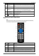
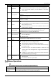
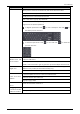
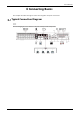
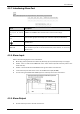
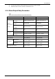
Table Of Contents
- Regulatory Information
- Foreword
- Important Safeguards and Warnings
- 1 Introduction
- 2 Getting Started
- 2.1 Checking the Components
- 2.2 Installing HDD
- 2.2.1 DH-XVR8216A-4KL-I/DH-XVR8208A-4K-I/DH-XVR8208A-4KL–I/DH-XVR7208A-4KL-I/DH-XVR7216A-4KL-I/DH-XVR52xxAN-I2/DH-XVR52xxA-I2/DH-XVR52xxAN-4KL-I2/DH-XVR52xxA-4KL-I2/DH-XVR72xxA-4K-I2/DH-XVR7216AN-4K-I2/DH-XVR4216AN-I
- 2.2.2 DH-XVR8816S-4KL-I/DH-XVR5808S-I2/DH-XVR5816S-I2/DH-XVR5832S-I2/DH-XVR5816S-4KL-I2/DH-XVR5832S-4KL-I2/DH-XVR7808S-4K-I2/DH-XVR7816S-4K-I2/DH-XVR5816S-4KL-I2-LP/DH-XVR7816S-4KL-X-LP-V2
- 2.2.3 DH-XVR5408L-I2/DH-XVR5416L-I2/DH-XVR5432L-I2/DH-XVR5416L-4KL-I2/DH-XVR5432L-4KL-I2/DH-XVR7408L-4K-I2/DH-XVR7416L-4K-I2
- 2.2.4 DH-XVR5104H-I/DH-XVR5108H-I/DH-XVR5116H-I/DH-XVR7104HE-4KL-I/DH-XVR7108HE-4KL-I/DH-XVR7116HE-4KL-I/DH-XVR51xxHS-I2/DH-XVR51xxH-I2/DH-XVR51xxHE-I2/DH-XVR51xxHS-4KL-I2/DH-XVR51xxH-4KL-I2/DH-XVR51xxHE-4KL-I2/DH-XVR71xxH-4K-I2/DH-XVR71xxHE-4K-I2/DH-...
- 2.2.5 DH-XVR5104C-I3/DH-XVR5108C-I3/DH-XVR5104C-4KL-I3
- 3 The Grand Tour
- 3.1 Front Panel
- 3.1.1 DH-XVR5104H-I/DH-XVR5108H-I/DH-XVR5116H-I
- 3.1.2 DH-XVR7104HE-4KL-I/DH-XVR7108HE-4KL-I/DH-XVR7116HE-4KL-I/DH-XVR71xxH-4K-I2/DH-XVR71xxHE-4K-I2
- 3.1.3 DH-XVR7208A-4KL-I/DH-XVR7216A-4KL-I/DH-XVR7216AN-4K-I2
- 3.1.4 DH-XVR8216A-4KL-I/DH-XVR8208A-4K-I/DH-XVR8208A-4KL–I
- 3.1.5 DH-XVR51xxHS-I2/DH-XVR51xxH-I2/DH-XVR51xxHE-I2/DH-XVR52xxAN-I2/DH-XVR52xxA-I2/DH-XVR51xxHS-4KL-I2/DH-XVR51xxH-4KL-I2/DH-XVR51xxHE-4KL-I2/DH-XVR52xxAN-4KL-I2/DH-XVR52xxA-4KL-I2/DH-XVR5104HS-I3/DH-XVR5104H-I3/DH-XVR5104HE-I3/DH-XVR5108HS-I3/DH-XVR...
- 3.1.6 DH-XVR8816S-4KL-I/DH-XVR7808S-4K-I2/DH-XVR7816S-4K-I2/DH-XVR7816S-4KL-X-LP-V2
- 3.1.7 DH-XVR7408L-4K-I2/DH-XVR7416L-4K-I2
- 3.1.8 DH-XVR5408L-I2/DH-XVR5416L-I2/DH-XVR5432L-I2/DH-XVR5416L-4KL-I2/DH-XVR5432L-4KL-I2
- 3.1.9 DH-XVR5808S-I2/DH-XVR5816S-I2/DH-XVR5832S-I2/DH-XVR5816S-4KL-I2/DH-XVR5832S-4KL-I2/DH-XVR5816S-4KL-I2-LP
- 3.1.10 DH-XVR1B08-I/DH-XVR1B08H-I/DH-XVR1B16-I/DH-XVR1B04-I/DH-XVR1B04H-I
- 3.1.11 DH-XVR5104C-I3/DH-XVR5108C-I3/DH-XVR5104C-4KL -I3
- 3.2 Rear Panel
- 3.2.1 DH-XVR5104H-I/DH-XVR5108H-I/DH-XVR5116H-I/DH-XVR7104HE-4KL-I/DH-XVR7108HE-4KL-I/DH-XVR7116HE-4KL-I/DH-XVR51xxH-I2/DH-XVR51xxHE-I2/DH-XVR51xxH-4KL-I2/DH-XVR51xxHE-4KL-I2//DH-XVR71xxH-4K-I2/DH-XVR71xxHE-4K-I2/DH-XVR5104H-I3/DH-XVR5104HE-I3/H-XVR51...
- 3.2.2 DH-XVR51xxHS-I2/DH-XVR51xxHS-4KL-I2/DH-XVR5104HS-I3/DH-XVR5108HS-I3/DH-XVR5104HS-4KL-I3/DH-XVR4104HS-I/DH-XVR4108HS-I/DH-XVR4104C-I/DH-XVR4108C-I/DH-XVR4116HS-I
- 3.2.3 DH-XVR7208A-4KL-I/DH-XVR7216A-4KL-I/DH-XVR52xxAN-I2/DH-XVR52xxA-I2/DH-XVR52xxAN-4KL-I2/DH-XVR-52xxA-4KL-I2/DH-XVR72xxA-4K-I2/DH-XVR7216AN-4K-I2/DH-XVR4216AN-I
- 3.2.4 DH-XVR8216A-4KL-I/DH-XVR8208A-4K-I/DH-XVR8208A-4KL–I
- 3.2.5 DH-XVR8816S-4KL-I/DH-XVR58xxS-I2/DH-XVR58xxS-4KL-I2/DH-XVR78xxS-4K-I2
- 3.2.6 DH-XVR5816S-4KL-I2-LP/DH-XVR7816S-4KL-X-LP-V2
- 3.2.7 DH-XVR5408L-I2/DH-XVR5416L-I2/DH-XVR5432L-I2/DH-XVR5416L-4KL-I2/DH-XVR5432L-4KL-I2/DH-XVR7408L-4K-I2/DH-XVR7416L-4K-I2
- 3.2.8 DH-XVR1B16-I/DH-XVR1B08-I/DH-XVR1B08H-I/DH-XVR1B04-I/DH-XVR1B04H-I
- 3.2.9 DH-XVR5104C-I3/DH-XVR5108C-I3/DH-XVR5104C-4KL -I3
- 3.3 Remote Control Operations
- 3.4 Mouse Operations
- 3.1 Front Panel
- 4 Connecting Basics
- 5 Local Configurations
- 5.1 Initial Settings
- 5.1.1 Booting up
- 5.1.2 Initializing the Device
- 5.1.3 Resetting Password
- 5.1.4 Setting Up with the Startup Wizard
- 5.1.4.1 Entering Startup Wizard
- 5.1.4.2 Configuring General Settings
- 5.1.4.3 Configuring Date and Time Settings
- 5.1.4.4 Configuring Network Settings
- 5.1.4.5 Configuring P2P Settings
- 5.1.4.6 Configuring Encode Settings
- 5.1.4.7 Configuring Snapshot Settings
- 5.1.4.8 Configuring Basic Storage Settings
- 5.1.4.9 Configuring Recorded Video Storage Schedule
- 5.1.4.10 Configuring Snapshot Storage Schedule
- 5.2 Live View
- 5.2.1 Live View Screen
- 5.2.2 Live View Control bar
- 5.2.2.1 Instant Playback
- 5.2.2.2 Digital Zoom
- 5.2.2.3 Instant Record
- 5.2.2.4 Manual Snapshot
- 5.2.2.5 Mute (Analog channel only)
- 5.2.2.6 White Light (Supported on camera with white light function)
- 5.2.2.7 Siren (Supported on camera with siren function)
- 5.2.2.8 Two-way Talk (Digital channel only)
- 5.2.2.9 Adding Camera (Digital channel only)
- 5.2.3 Navigation Bar
- 5.2.4 Shortcut Menu
- 5.2.5 AI Preview Mode
- 5.2.6 Channel Sequence
- 5.2.7 Color Setting
- 5.2.8 Live View Display
- 5.2.9 Configuring Tour Settings
- 5.2.10 Quick Operation Bar
- 5.3 Entering Main Menu
- 5.4 Controlling PTZ Cameras
- 5.5 Configuring Camera Settings
- 5.6 Configuring Remote Devices
- 5.7 Configuring Record Settings
- 5.8 Configuring Snapshot Settings
- 5.9 Playing Back Video
- 5.10 Alarm Events Settings
- 5.11 AI Function
- 5.11.1 For Pro AI Series
- 5.11.2 For Lite AI Series
- 5.12 IoT Function
- 5.12.1 Configuring Sensor Settings
- 5.12.2 Configuring Temperature and Humidity Camera
- 5.12.3 Configuring Wireless Siren
- 5.13 Configuring POS Settings
- 5.14 Configuring Backup Settings
- 5.15 Network Management
- 5.15.1 Configuring Network Settings
- 5.15.1.1 Configuring TCP/IP Settings
- 5.15.1.2 Configuring Port Settings
- 5.15.1.3 Configuring Wi-Fi Connection Settings
- 5.15.1.4 Configuring 3G/4G Settings
- 5.15.1.5 Configuring PPPoE Settings
- 5.15.1.6 Configuring DDNS Settings
- 5.15.1.7 Configuring EMAIL Settings
- 5.15.1.8 Configuring UPnP Settings
- 5.15.1.9 Configuring SNMP Settings
- 5.15.1.10 Configuring Multicast Settings
- 5.15.1.11 Configuring Register Settings
- 5.15.1.12 Configuring Alarm Center Settings
- 5.15.1.13 Configuring P2P Settings
- 5.15.2 Configuring Network Testing Settings
- 5.15.1 Configuring Network Settings
- 5.16 Configuring Account Settings
- 5.17 Audio Management
- 5.18 Storage Management
- 5.18.1 Configuring Basic Settings
- 5.18.2 Configuring the Recording and Snapshot Schedule
- 5.18.3 Configuring Disk Manager
- 5.18.4 Configuring Record
- 5.18.5 Configuring Advance Settings
- 5.18.6 Configuring Disk Quota
- 5.18.7 Configuring HDD Detecting Settings
- 5.18.8 Configuring Record Estimate
- 5.18.9 Configuring FTP Storage Settings
- 5.19 Security Center
- 5.20 Configuring System Settings
- 5.21 Viewing Information
- 5.22 Logout the Device
- 5.1 Initial Settings
- 6 Web Operations
- 7 FAQ
- Appendix 1 Glossary
- Appendix 2 HDD Capacity Calculation
- Appendix 3 Compatible Backup Devices
- Appendix 4 Compatible CD/DVD Burner List
- Appendix 5 Compatible Displayer List
- Appendix 6 Compatible Switcher
- Appendix 7 Earthing
- Appendix 8 RJ45-RS-232 Connection Cable Definition
- Appendix 9 Cybersecurity Recommendations

User’s Manual
36
Due to high impedance of audio input, please use active sound pick-up.
Audio transmission is similar to video transmission. Try to avoid interference, dry joint, loose contact
and it shall be away from high tension current.
4.2.4 Audio Output
The audio output signal parameter is usually over 200mv 1KΩ (BNC or RCA). It can directly connect to
low impedance earphone, active sound box or amplifier-drive audio output device.
If the sound box and the pick-up cannot be separated spatially, it is easy to arouse squeaking. In this
case you can adopt the following measures:
Use better sound pick-up with better directing property.
Reduce the volume of the sound box.
Using more sound-absorbing materials in decoration can reduce voice echo and improve
acoustics environment.
Adjust the layout of speaker and pickup to reduce squeaking.
Connecting to Alarm Input and Output
Please read the followings before connecting.
Alarm input
Make sure alarm input mode is grounding alarm input.
Grounding signal is needed for alarm input.
Alarm input needs the low level voltage signal.
Alarm input mode can be either NC (Normally Closed) or NO (Normally Open).
When you are connecting two DVRs or you are connecting one DVR and one other device, use a
relay to separate them.
Alarm output
The alarm output port should not be connected to high power load directly (It shall be less than 1A)
to avoid high current which might result in relay damage. Use the contactor to realize the connection
between the alarm output port and the load.
How to connect PTZ decoder
Ensure the decoder has the same grounding with DVR; otherwise the PTZ might not be controlled.
Shielded twisted wire is recommended and the shielded layer is used to connect to the grounding.
Avoid high voltage. Ensure proper wiring and some thunder protection measures.
For too long signal wires, 120Ω should be parallel connected between A, B lines on the far end to
reduce reflection and guarantee the signal quality.
“485 A, B” of DVR cannot parallel connect with“485 port” of other device.
The voltage between of A, B lines of the decoder should be less than 5V.
Make sure the front-end device has soundly earthed
Improper grounding might result in chip damage.