
User Manual
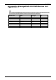
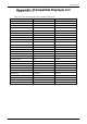
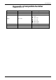
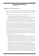

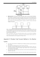
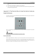
Table Of Contents
- Regulatory Information
- Foreword
- Important Safeguards and Warnings
- 1 Introduction
- 2 Getting Started
- 2.1 Checking the Components
- 2.2 Installing HDD
- 2.2.1 DH-XVR8216A-4KL-I/DH-XVR8208A-4K-I/DH-XVR8208A-4KL–I/DH-XVR7208A-4KL-I/DH-XVR7216A-4KL-I/DH-XVR52xxAN-I2/DH-XVR52xxA-I2/DH-XVR52xxAN-4KL-I2/DH-XVR52xxA-4KL-I2/DH-XVR72xxA-4K-I2/DH-XVR7216AN-4K-I2/DH-XVR4216AN-I
- 2.2.2 DH-XVR8816S-4KL-I/DH-XVR5808S-I2/DH-XVR5816S-I2/DH-XVR5832S-I2/DH-XVR5816S-4KL-I2/DH-XVR5832S-4KL-I2/DH-XVR7808S-4K-I2/DH-XVR7816S-4K-I2/DH-XVR5816S-4KL-I2-LP/DH-XVR7816S-4KL-X-LP-V2
- 2.2.3 DH-XVR5408L-I2/DH-XVR5416L-I2/DH-XVR5432L-I2/DH-XVR5416L-4KL-I2/DH-XVR5432L-4KL-I2/DH-XVR7408L-4K-I2/DH-XVR7416L-4K-I2
- 2.2.4 DH-XVR5104H-I/DH-XVR5108H-I/DH-XVR5116H-I/DH-XVR7104HE-4KL-I/DH-XVR7108HE-4KL-I/DH-XVR7116HE-4KL-I/DH-XVR51xxHS-I2/DH-XVR51xxH-I2/DH-XVR51xxHE-I2/DH-XVR51xxHS-4KL-I2/DH-XVR51xxH-4KL-I2/DH-XVR51xxHE-4KL-I2/DH-XVR71xxH-4K-I2/DH-XVR71xxHE-4K-I2/DH-...
- 2.2.5 DH-XVR5104C-I3/DH-XVR5108C-I3/DH-XVR5104C-4KL-I3
- 3 The Grand Tour
- 3.1 Front Panel
- 3.1.1 DH-XVR5104H-I/DH-XVR5108H-I/DH-XVR5116H-I
- 3.1.2 DH-XVR7104HE-4KL-I/DH-XVR7108HE-4KL-I/DH-XVR7116HE-4KL-I/DH-XVR71xxH-4K-I2/DH-XVR71xxHE-4K-I2
- 3.1.3 DH-XVR7208A-4KL-I/DH-XVR7216A-4KL-I/DH-XVR7216AN-4K-I2
- 3.1.4 DH-XVR8216A-4KL-I/DH-XVR8208A-4K-I/DH-XVR8208A-4KL–I
- 3.1.5 DH-XVR51xxHS-I2/DH-XVR51xxH-I2/DH-XVR51xxHE-I2/DH-XVR52xxAN-I2/DH-XVR52xxA-I2/DH-XVR51xxHS-4KL-I2/DH-XVR51xxH-4KL-I2/DH-XVR51xxHE-4KL-I2/DH-XVR52xxAN-4KL-I2/DH-XVR52xxA-4KL-I2/DH-XVR5104HS-I3/DH-XVR5104H-I3/DH-XVR5104HE-I3/DH-XVR5108HS-I3/DH-XVR...
- 3.1.6 DH-XVR8816S-4KL-I/DH-XVR7808S-4K-I2/DH-XVR7816S-4K-I2/DH-XVR7816S-4KL-X-LP-V2
- 3.1.7 DH-XVR7408L-4K-I2/DH-XVR7416L-4K-I2
- 3.1.8 DH-XVR5408L-I2/DH-XVR5416L-I2/DH-XVR5432L-I2/DH-XVR5416L-4KL-I2/DH-XVR5432L-4KL-I2
- 3.1.9 DH-XVR5808S-I2/DH-XVR5816S-I2/DH-XVR5832S-I2/DH-XVR5816S-4KL-I2/DH-XVR5832S-4KL-I2/DH-XVR5816S-4KL-I2-LP
- 3.1.10 DH-XVR1B08-I/DH-XVR1B08H-I/DH-XVR1B16-I/DH-XVR1B04-I/DH-XVR1B04H-I
- 3.1.11 DH-XVR5104C-I3/DH-XVR5108C-I3/DH-XVR5104C-4KL -I3
- 3.2 Rear Panel
- 3.2.1 DH-XVR5104H-I/DH-XVR5108H-I/DH-XVR5116H-I/DH-XVR7104HE-4KL-I/DH-XVR7108HE-4KL-I/DH-XVR7116HE-4KL-I/DH-XVR51xxH-I2/DH-XVR51xxHE-I2/DH-XVR51xxH-4KL-I2/DH-XVR51xxHE-4KL-I2//DH-XVR71xxH-4K-I2/DH-XVR71xxHE-4K-I2/DH-XVR5104H-I3/DH-XVR5104HE-I3/H-XVR51...
- 3.2.2 DH-XVR51xxHS-I2/DH-XVR51xxHS-4KL-I2/DH-XVR5104HS-I3/DH-XVR5108HS-I3/DH-XVR5104HS-4KL-I3/DH-XVR4104HS-I/DH-XVR4108HS-I/DH-XVR4104C-I/DH-XVR4108C-I/DH-XVR4116HS-I
- 3.2.3 DH-XVR7208A-4KL-I/DH-XVR7216A-4KL-I/DH-XVR52xxAN-I2/DH-XVR52xxA-I2/DH-XVR52xxAN-4KL-I2/DH-XVR-52xxA-4KL-I2/DH-XVR72xxA-4K-I2/DH-XVR7216AN-4K-I2/DH-XVR4216AN-I
- 3.2.4 DH-XVR8216A-4KL-I/DH-XVR8208A-4K-I/DH-XVR8208A-4KL–I
- 3.2.5 DH-XVR8816S-4KL-I/DH-XVR58xxS-I2/DH-XVR58xxS-4KL-I2/DH-XVR78xxS-4K-I2
- 3.2.6 DH-XVR5816S-4KL-I2-LP/DH-XVR7816S-4KL-X-LP-V2
- 3.2.7 DH-XVR5408L-I2/DH-XVR5416L-I2/DH-XVR5432L-I2/DH-XVR5416L-4KL-I2/DH-XVR5432L-4KL-I2/DH-XVR7408L-4K-I2/DH-XVR7416L-4K-I2
- 3.2.8 DH-XVR1B16-I/DH-XVR1B08-I/DH-XVR1B08H-I/DH-XVR1B04-I/DH-XVR1B04H-I
- 3.2.9 DH-XVR5104C-I3/DH-XVR5108C-I3/DH-XVR5104C-4KL -I3
- 3.3 Remote Control Operations
- 3.4 Mouse Operations
- 3.1 Front Panel
- 4 Connecting Basics
- 5 Local Configurations
- 5.1 Initial Settings
- 5.1.1 Booting up
- 5.1.2 Initializing the Device
- 5.1.3 Resetting Password
- 5.1.4 Setting Up with the Startup Wizard
- 5.1.4.1 Entering Startup Wizard
- 5.1.4.2 Configuring General Settings
- 5.1.4.3 Configuring Date and Time Settings
- 5.1.4.4 Configuring Network Settings
- 5.1.4.5 Configuring P2P Settings
- 5.1.4.6 Configuring Encode Settings
- 5.1.4.7 Configuring Snapshot Settings
- 5.1.4.8 Configuring Basic Storage Settings
- 5.1.4.9 Configuring Recorded Video Storage Schedule
- 5.1.4.10 Configuring Snapshot Storage Schedule
- 5.2 Live View
- 5.2.1 Live View Screen
- 5.2.2 Live View Control bar
- 5.2.2.1 Instant Playback
- 5.2.2.2 Digital Zoom
- 5.2.2.3 Instant Record
- 5.2.2.4 Manual Snapshot
- 5.2.2.5 Mute (Analog channel only)
- 5.2.2.6 White Light (Supported on camera with white light function)
- 5.2.2.7 Siren (Supported on camera with siren function)
- 5.2.2.8 Two-way Talk (Digital channel only)
- 5.2.2.9 Adding Camera (Digital channel only)
- 5.2.3 Navigation Bar
- 5.2.4 Shortcut Menu
- 5.2.5 AI Preview Mode
- 5.2.6 Channel Sequence
- 5.2.7 Color Setting
- 5.2.8 Live View Display
- 5.2.9 Configuring Tour Settings
- 5.2.10 Quick Operation Bar
- 5.3 Entering Main Menu
- 5.4 Controlling PTZ Cameras
- 5.5 Configuring Camera Settings
- 5.6 Configuring Remote Devices
- 5.7 Configuring Record Settings
- 5.8 Configuring Snapshot Settings
- 5.9 Playing Back Video
- 5.10 Alarm Events Settings
- 5.11 AI Function
- 5.11.1 For Pro AI Series
- 5.11.2 For Lite AI Series
- 5.12 IoT Function
- 5.12.1 Configuring Sensor Settings
- 5.12.2 Configuring Temperature and Humidity Camera
- 5.12.3 Configuring Wireless Siren
- 5.13 Configuring POS Settings
- 5.14 Configuring Backup Settings
- 5.15 Network Management
- 5.15.1 Configuring Network Settings
- 5.15.1.1 Configuring TCP/IP Settings
- 5.15.1.2 Configuring Port Settings
- 5.15.1.3 Configuring Wi-Fi Connection Settings
- 5.15.1.4 Configuring 3G/4G Settings
- 5.15.1.5 Configuring PPPoE Settings
- 5.15.1.6 Configuring DDNS Settings
- 5.15.1.7 Configuring EMAIL Settings
- 5.15.1.8 Configuring UPnP Settings
- 5.15.1.9 Configuring SNMP Settings
- 5.15.1.10 Configuring Multicast Settings
- 5.15.1.11 Configuring Register Settings
- 5.15.1.12 Configuring Alarm Center Settings
- 5.15.1.13 Configuring P2P Settings
- 5.15.2 Configuring Network Testing Settings
- 5.15.1 Configuring Network Settings
- 5.16 Configuring Account Settings
- 5.17 Audio Management
- 5.18 Storage Management
- 5.18.1 Configuring Basic Settings
- 5.18.2 Configuring the Recording and Snapshot Schedule
- 5.18.3 Configuring Disk Manager
- 5.18.4 Configuring Record
- 5.18.5 Configuring Advance Settings
- 5.18.6 Configuring Disk Quota
- 5.18.7 Configuring HDD Detecting Settings
- 5.18.8 Configuring Record Estimate
- 5.18.9 Configuring FTP Storage Settings
- 5.19 Security Center
- 5.20 Configuring System Settings
- 5.21 Viewing Information
- 5.22 Logout the Device
- 5.1 Initial Settings
- 6 Web Operations
- 7 FAQ
- Appendix 1 Glossary
- Appendix 2 HDD Capacity Calculation
- Appendix 3 Compatible Backup Devices
- Appendix 4 Compatible CD/DVD Burner List
- Appendix 5 Compatible Displayer List
- Appendix 6 Compatible Switcher
- Appendix 7 Earthing
- Appendix 8 RJ45-RS-232 Connection Cable Definition
- Appendix 9 Cybersecurity Recommendations

User’s Manual
366
Mixed ground: The mix ground consists of the feature of the one-point ground and multiple-
point ground. For example, the power in the system needs to use the one-point ground mode
while the radio frequency signal requires the multiple-point ground. So, you can use the following
figure to earth. For the direct current (DC), the capacitance is open circuit and the circuit is one-
point ground. For the radio frequency signal, the capacitance is conducive and the circuit adopts
multiple-point ground.
When connecting devices of huge size (the device physical dimension and connection cable is big
c
omparing with the wave path of existed interference), then there is possibility of interference when
the current goes through the chassis and cable. In this situation, the interference circuit path usually
lies in the system ground circuit.
When considering the earthing, you need to think about two aspects: One is the system compatibility,
and the other is the external interference coupling into the earth circuit, which results in system error.
For the external interference is not regular, it is not easy to resolve.
Appendix 7.3 Thunder Proof Ground Method in the Monitor
System
The monitor system shall have sound thunder proof earthing to guarantee personnel safety and
device safety.
The monitor system working ground resistance shall be less than 1Ω.
The thunder proof ground shall adopt the special ground cable from the monitor control room
to the ground object. The ground cable adopts copper insulation cable or wire and its ground
section shall be more than 20mm
2
.
The ground cable of the monitor system cannot short circuit or mixed connected with the strong
alternative current cable.
For all the ground cables from the control room to the monitor system or ground cable of other