
User Manual
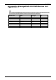
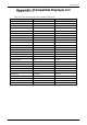
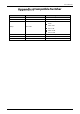
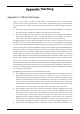

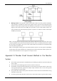
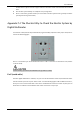

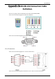
Table Of Contents
- Regulatory Information
- Foreword
- Important Safeguards and Warnings
- 1 Introduction
- 2 Getting Started
- 2.1 Checking the Components
- 2.2 Installing HDD
- 2.2.1 DH-XVR8216A-4KL-I/DH-XVR8208A-4K-I/DH-XVR8208A-4KL–I/DH-XVR7208A-4KL-I/DH-XVR7216A-4KL-I/DH-XVR52xxAN-I2/DH-XVR52xxA-I2/DH-XVR52xxAN-4KL-I2/DH-XVR52xxA-4KL-I2/DH-XVR72xxA-4K-I2/DH-XVR7216AN-4K-I2/DH-XVR4216AN-I
- 2.2.2 DH-XVR8816S-4KL-I/DH-XVR5808S-I2/DH-XVR5816S-I2/DH-XVR5832S-I2/DH-XVR5816S-4KL-I2/DH-XVR5832S-4KL-I2/DH-XVR7808S-4K-I2/DH-XVR7816S-4K-I2/DH-XVR5816S-4KL-I2-LP/DH-XVR7816S-4KL-X-LP-V2
- 2.2.3 DH-XVR5408L-I2/DH-XVR5416L-I2/DH-XVR5432L-I2/DH-XVR5416L-4KL-I2/DH-XVR5432L-4KL-I2/DH-XVR7408L-4K-I2/DH-XVR7416L-4K-I2
- 2.2.4 DH-XVR5104H-I/DH-XVR5108H-I/DH-XVR5116H-I/DH-XVR7104HE-4KL-I/DH-XVR7108HE-4KL-I/DH-XVR7116HE-4KL-I/DH-XVR51xxHS-I2/DH-XVR51xxH-I2/DH-XVR51xxHE-I2/DH-XVR51xxHS-4KL-I2/DH-XVR51xxH-4KL-I2/DH-XVR51xxHE-4KL-I2/DH-XVR71xxH-4K-I2/DH-XVR71xxHE-4K-I2/DH-...
- 2.2.5 DH-XVR5104C-I3/DH-XVR5108C-I3/DH-XVR5104C-4KL-I3
- 3 The Grand Tour
- 3.1 Front Panel
- 3.1.1 DH-XVR5104H-I/DH-XVR5108H-I/DH-XVR5116H-I
- 3.1.2 DH-XVR7104HE-4KL-I/DH-XVR7108HE-4KL-I/DH-XVR7116HE-4KL-I/DH-XVR71xxH-4K-I2/DH-XVR71xxHE-4K-I2
- 3.1.3 DH-XVR7208A-4KL-I/DH-XVR7216A-4KL-I/DH-XVR7216AN-4K-I2
- 3.1.4 DH-XVR8216A-4KL-I/DH-XVR8208A-4K-I/DH-XVR8208A-4KL–I
- 3.1.5 DH-XVR51xxHS-I2/DH-XVR51xxH-I2/DH-XVR51xxHE-I2/DH-XVR52xxAN-I2/DH-XVR52xxA-I2/DH-XVR51xxHS-4KL-I2/DH-XVR51xxH-4KL-I2/DH-XVR51xxHE-4KL-I2/DH-XVR52xxAN-4KL-I2/DH-XVR52xxA-4KL-I2/DH-XVR5104HS-I3/DH-XVR5104H-I3/DH-XVR5104HE-I3/DH-XVR5108HS-I3/DH-XVR...
- 3.1.6 DH-XVR8816S-4KL-I/DH-XVR7808S-4K-I2/DH-XVR7816S-4K-I2/DH-XVR7816S-4KL-X-LP-V2
- 3.1.7 DH-XVR7408L-4K-I2/DH-XVR7416L-4K-I2
- 3.1.8 DH-XVR5408L-I2/DH-XVR5416L-I2/DH-XVR5432L-I2/DH-XVR5416L-4KL-I2/DH-XVR5432L-4KL-I2
- 3.1.9 DH-XVR5808S-I2/DH-XVR5816S-I2/DH-XVR5832S-I2/DH-XVR5816S-4KL-I2/DH-XVR5832S-4KL-I2/DH-XVR5816S-4KL-I2-LP
- 3.1.10 DH-XVR1B08-I/DH-XVR1B08H-I/DH-XVR1B16-I/DH-XVR1B04-I/DH-XVR1B04H-I
- 3.1.11 DH-XVR5104C-I3/DH-XVR5108C-I3/DH-XVR5104C-4KL -I3
- 3.2 Rear Panel
- 3.2.1 DH-XVR5104H-I/DH-XVR5108H-I/DH-XVR5116H-I/DH-XVR7104HE-4KL-I/DH-XVR7108HE-4KL-I/DH-XVR7116HE-4KL-I/DH-XVR51xxH-I2/DH-XVR51xxHE-I2/DH-XVR51xxH-4KL-I2/DH-XVR51xxHE-4KL-I2//DH-XVR71xxH-4K-I2/DH-XVR71xxHE-4K-I2/DH-XVR5104H-I3/DH-XVR5104HE-I3/H-XVR51...
- 3.2.2 DH-XVR51xxHS-I2/DH-XVR51xxHS-4KL-I2/DH-XVR5104HS-I3/DH-XVR5108HS-I3/DH-XVR5104HS-4KL-I3/DH-XVR4104HS-I/DH-XVR4108HS-I/DH-XVR4104C-I/DH-XVR4108C-I/DH-XVR4116HS-I
- 3.2.3 DH-XVR7208A-4KL-I/DH-XVR7216A-4KL-I/DH-XVR52xxAN-I2/DH-XVR52xxA-I2/DH-XVR52xxAN-4KL-I2/DH-XVR-52xxA-4KL-I2/DH-XVR72xxA-4K-I2/DH-XVR7216AN-4K-I2/DH-XVR4216AN-I
- 3.2.4 DH-XVR8216A-4KL-I/DH-XVR8208A-4K-I/DH-XVR8208A-4KL–I
- 3.2.5 DH-XVR8816S-4KL-I/DH-XVR58xxS-I2/DH-XVR58xxS-4KL-I2/DH-XVR78xxS-4K-I2
- 3.2.6 DH-XVR5816S-4KL-I2-LP/DH-XVR7816S-4KL-X-LP-V2
- 3.2.7 DH-XVR5408L-I2/DH-XVR5416L-I2/DH-XVR5432L-I2/DH-XVR5416L-4KL-I2/DH-XVR5432L-4KL-I2/DH-XVR7408L-4K-I2/DH-XVR7416L-4K-I2
- 3.2.8 DH-XVR1B16-I/DH-XVR1B08-I/DH-XVR1B08H-I/DH-XVR1B04-I/DH-XVR1B04H-I
- 3.2.9 DH-XVR5104C-I3/DH-XVR5108C-I3/DH-XVR5104C-4KL -I3
- 3.3 Remote Control Operations
- 3.4 Mouse Operations
- 3.1 Front Panel
- 4 Connecting Basics
- 5 Local Configurations
- 5.1 Initial Settings
- 5.1.1 Booting up
- 5.1.2 Initializing the Device
- 5.1.3 Resetting Password
- 5.1.4 Setting Up with the Startup Wizard
- 5.1.4.1 Entering Startup Wizard
- 5.1.4.2 Configuring General Settings
- 5.1.4.3 Configuring Date and Time Settings
- 5.1.4.4 Configuring Network Settings
- 5.1.4.5 Configuring P2P Settings
- 5.1.4.6 Configuring Encode Settings
- 5.1.4.7 Configuring Snapshot Settings
- 5.1.4.8 Configuring Basic Storage Settings
- 5.1.4.9 Configuring Recorded Video Storage Schedule
- 5.1.4.10 Configuring Snapshot Storage Schedule
- 5.2 Live View
- 5.2.1 Live View Screen
- 5.2.2 Live View Control bar
- 5.2.2.1 Instant Playback
- 5.2.2.2 Digital Zoom
- 5.2.2.3 Instant Record
- 5.2.2.4 Manual Snapshot
- 5.2.2.5 Mute (Analog channel only)
- 5.2.2.6 White Light (Supported on camera with white light function)
- 5.2.2.7 Siren (Supported on camera with siren function)
- 5.2.2.8 Two-way Talk (Digital channel only)
- 5.2.2.9 Adding Camera (Digital channel only)
- 5.2.3 Navigation Bar
- 5.2.4 Shortcut Menu
- 5.2.5 AI Preview Mode
- 5.2.6 Channel Sequence
- 5.2.7 Color Setting
- 5.2.8 Live View Display
- 5.2.9 Configuring Tour Settings
- 5.2.10 Quick Operation Bar
- 5.3 Entering Main Menu
- 5.4 Controlling PTZ Cameras
- 5.5 Configuring Camera Settings
- 5.6 Configuring Remote Devices
- 5.7 Configuring Record Settings
- 5.8 Configuring Snapshot Settings
- 5.9 Playing Back Video
- 5.10 Alarm Events Settings
- 5.11 AI Function
- 5.11.1 For Pro AI Series
- 5.11.2 For Lite AI Series
- 5.12 IoT Function
- 5.12.1 Configuring Sensor Settings
- 5.12.2 Configuring Temperature and Humidity Camera
- 5.12.3 Configuring Wireless Siren
- 5.13 Configuring POS Settings
- 5.14 Configuring Backup Settings
- 5.15 Network Management
- 5.15.1 Configuring Network Settings
- 5.15.1.1 Configuring TCP/IP Settings
- 5.15.1.2 Configuring Port Settings
- 5.15.1.3 Configuring Wi-Fi Connection Settings
- 5.15.1.4 Configuring 3G/4G Settings
- 5.15.1.5 Configuring PPPoE Settings
- 5.15.1.6 Configuring DDNS Settings
- 5.15.1.7 Configuring EMAIL Settings
- 5.15.1.8 Configuring UPnP Settings
- 5.15.1.9 Configuring SNMP Settings
- 5.15.1.10 Configuring Multicast Settings
- 5.15.1.11 Configuring Register Settings
- 5.15.1.12 Configuring Alarm Center Settings
- 5.15.1.13 Configuring P2P Settings
- 5.15.2 Configuring Network Testing Settings
- 5.15.1 Configuring Network Settings
- 5.16 Configuring Account Settings
- 5.17 Audio Management
- 5.18 Storage Management
- 5.18.1 Configuring Basic Settings
- 5.18.2 Configuring the Recording and Snapshot Schedule
- 5.18.3 Configuring Disk Manager
- 5.18.4 Configuring Record
- 5.18.5 Configuring Advance Settings
- 5.18.6 Configuring Disk Quota
- 5.18.7 Configuring HDD Detecting Settings
- 5.18.8 Configuring Record Estimate
- 5.18.9 Configuring FTP Storage Settings
- 5.19 Security Center
- 5.20 Configuring System Settings
- 5.21 Viewing Information
- 5.22 Logout the Device
- 5.1 Initial Settings
- 6 Web Operations
- 7 FAQ
- Appendix 1 Glossary
- Appendix 2 HDD Capacity Calculation
- Appendix 3 Compatible Backup Devices
- Appendix 4 Compatible CD/DVD Burner List
- Appendix 5 Compatible Displayer List
- Appendix 6 Compatible Switcher
- Appendix 7 Earthing
- Appendix 8 RJ45-RS-232 Connection Cable Definition
- Appendix 9 Cybersecurity Recommendations

User’s Manual
365
device system to receive the wireless signal. It uses the serial connection too.
Please note, when you select the lighting arrester, please pay attention to the port type and the
earthing reliability. In some important environment, you need to use special shielded cable. Do not
parallel connect the thunder proof ground cable with the ground cable of the lightning rod. Please
make sure they are far enough and grounded respectively.
Appendix 7.2 The Earthing Modes
We all know the earthing is the most complicated technology in the electromagnetism compatibility
design since there is no systematic theory or module. The earthing has many modes, but the selection
depends on the system structure and performance.
The following are some successfully experience from our past work.
One-point ground: In the following figure you can see there is a one-point ground. This
connection provides common point to allow signal to be transmitted in many circuits. If there is
no common point, the error signal transmission occurred. In the one-point ground mode, each
circuit is just grounded only and they are connected at the same point. Since there is only one
common point, there is no circuit and so, there is no interference.
Multiple-point ground: In the following figure, you can see the internal circuit uses the chassis
as the common point. While at the same time, all devices chassis use the earthing as the common
point. In this connection, the ground structure can provide the lower ground resistance because
when there are multiple-point grounds; each ground cable is as short as possible. And the parallel
cable connection can reduce the total conductance of the ground conductor. In the high-
frequency circuit, you need to use the multiple-point ground mode and each cable needs to
connect to the ground. The length shall be less than the 1/20 of the signal wavelength.