
User Manual
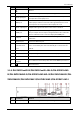
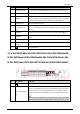

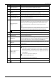
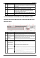
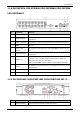
Table Of Contents
- Regulatory Information
- Foreword
- Important Safeguards and Warnings
- 1 Introduction
- 2 Getting Started
- 2.1 Checking the Components
- 2.2 Installing HDD
- 2.2.1 DH-XVR8216A-4KL-I/DH-XVR8208A-4K-I/DH-XVR8208A-4KL–I/DH-XVR7208A-4KL-I/DH-XVR7216A-4KL-I/DH-XVR52xxAN-I2/DH-XVR52xxA-I2/DH-XVR52xxAN-4KL-I2/DH-XVR52xxA-4KL-I2/DH-XVR72xxA-4K-I2/DH-XVR7216AN-4K-I2/DH-XVR4216AN-I
- 2.2.2 DH-XVR8816S-4KL-I/DH-XVR5808S-I2/DH-XVR5816S-I2/DH-XVR5832S-I2/DH-XVR5816S-4KL-I2/DH-XVR5832S-4KL-I2/DH-XVR7808S-4K-I2/DH-XVR7816S-4K-I2/DH-XVR5816S-4KL-I2-LP/DH-XVR7816S-4KL-X-LP-V2
- 2.2.3 DH-XVR5408L-I2/DH-XVR5416L-I2/DH-XVR5432L-I2/DH-XVR5416L-4KL-I2/DH-XVR5432L-4KL-I2/DH-XVR7408L-4K-I2/DH-XVR7416L-4K-I2
- 2.2.4 DH-XVR5104H-I/DH-XVR5108H-I/DH-XVR5116H-I/DH-XVR7104HE-4KL-I/DH-XVR7108HE-4KL-I/DH-XVR7116HE-4KL-I/DH-XVR51xxHS-I2/DH-XVR51xxH-I2/DH-XVR51xxHE-I2/DH-XVR51xxHS-4KL-I2/DH-XVR51xxH-4KL-I2/DH-XVR51xxHE-4KL-I2/DH-XVR71xxH-4K-I2/DH-XVR71xxHE-4K-I2/DH-...
- 2.2.5 DH-XVR5104C-I3/DH-XVR5108C-I3/DH-XVR5104C-4KL-I3
- 3 The Grand Tour
- 3.1 Front Panel
- 3.1.1 DH-XVR5104H-I/DH-XVR5108H-I/DH-XVR5116H-I
- 3.1.2 DH-XVR7104HE-4KL-I/DH-XVR7108HE-4KL-I/DH-XVR7116HE-4KL-I/DH-XVR71xxH-4K-I2/DH-XVR71xxHE-4K-I2
- 3.1.3 DH-XVR7208A-4KL-I/DH-XVR7216A-4KL-I/DH-XVR7216AN-4K-I2
- 3.1.4 DH-XVR8216A-4KL-I/DH-XVR8208A-4K-I/DH-XVR8208A-4KL–I
- 3.1.5 DH-XVR51xxHS-I2/DH-XVR51xxH-I2/DH-XVR51xxHE-I2/DH-XVR52xxAN-I2/DH-XVR52xxA-I2/DH-XVR51xxHS-4KL-I2/DH-XVR51xxH-4KL-I2/DH-XVR51xxHE-4KL-I2/DH-XVR52xxAN-4KL-I2/DH-XVR52xxA-4KL-I2/DH-XVR5104HS-I3/DH-XVR5104H-I3/DH-XVR5104HE-I3/DH-XVR5108HS-I3/DH-XVR...
- 3.1.6 DH-XVR8816S-4KL-I/DH-XVR7808S-4K-I2/DH-XVR7816S-4K-I2/DH-XVR7816S-4KL-X-LP-V2
- 3.1.7 DH-XVR7408L-4K-I2/DH-XVR7416L-4K-I2
- 3.1.8 DH-XVR5408L-I2/DH-XVR5416L-I2/DH-XVR5432L-I2/DH-XVR5416L-4KL-I2/DH-XVR5432L-4KL-I2
- 3.1.9 DH-XVR5808S-I2/DH-XVR5816S-I2/DH-XVR5832S-I2/DH-XVR5816S-4KL-I2/DH-XVR5832S-4KL-I2/DH-XVR5816S-4KL-I2-LP
- 3.1.10 DH-XVR1B08-I/DH-XVR1B08H-I/DH-XVR1B16-I/DH-XVR1B04-I/DH-XVR1B04H-I
- 3.1.11 DH-XVR5104C-I3/DH-XVR5108C-I3/DH-XVR5104C-4KL -I3
- 3.2 Rear Panel
- 3.2.1 DH-XVR5104H-I/DH-XVR5108H-I/DH-XVR5116H-I/DH-XVR7104HE-4KL-I/DH-XVR7108HE-4KL-I/DH-XVR7116HE-4KL-I/DH-XVR51xxH-I2/DH-XVR51xxHE-I2/DH-XVR51xxH-4KL-I2/DH-XVR51xxHE-4KL-I2//DH-XVR71xxH-4K-I2/DH-XVR71xxHE-4K-I2/DH-XVR5104H-I3/DH-XVR5104HE-I3/H-XVR51...
- 3.2.2 DH-XVR51xxHS-I2/DH-XVR51xxHS-4KL-I2/DH-XVR5104HS-I3/DH-XVR5108HS-I3/DH-XVR5104HS-4KL-I3/DH-XVR4104HS-I/DH-XVR4108HS-I/DH-XVR4104C-I/DH-XVR4108C-I/DH-XVR4116HS-I
- 3.2.3 DH-XVR7208A-4KL-I/DH-XVR7216A-4KL-I/DH-XVR52xxAN-I2/DH-XVR52xxA-I2/DH-XVR52xxAN-4KL-I2/DH-XVR-52xxA-4KL-I2/DH-XVR72xxA-4K-I2/DH-XVR7216AN-4K-I2/DH-XVR4216AN-I
- 3.2.4 DH-XVR8216A-4KL-I/DH-XVR8208A-4K-I/DH-XVR8208A-4KL–I
- 3.2.5 DH-XVR8816S-4KL-I/DH-XVR58xxS-I2/DH-XVR58xxS-4KL-I2/DH-XVR78xxS-4K-I2
- 3.2.6 DH-XVR5816S-4KL-I2-LP/DH-XVR7816S-4KL-X-LP-V2
- 3.2.7 DH-XVR5408L-I2/DH-XVR5416L-I2/DH-XVR5432L-I2/DH-XVR5416L-4KL-I2/DH-XVR5432L-4KL-I2/DH-XVR7408L-4K-I2/DH-XVR7416L-4K-I2
- 3.2.8 DH-XVR1B16-I/DH-XVR1B08-I/DH-XVR1B08H-I/DH-XVR1B04-I/DH-XVR1B04H-I
- 3.2.9 DH-XVR5104C-I3/DH-XVR5108C-I3/DH-XVR5104C-4KL -I3
- 3.3 Remote Control Operations
- 3.4 Mouse Operations
- 3.1 Front Panel
- 4 Connecting Basics
- 5 Local Configurations
- 5.1 Initial Settings
- 5.1.1 Booting up
- 5.1.2 Initializing the Device
- 5.1.3 Resetting Password
- 5.1.4 Setting Up with the Startup Wizard
- 5.1.4.1 Entering Startup Wizard
- 5.1.4.2 Configuring General Settings
- 5.1.4.3 Configuring Date and Time Settings
- 5.1.4.4 Configuring Network Settings
- 5.1.4.5 Configuring P2P Settings
- 5.1.4.6 Configuring Encode Settings
- 5.1.4.7 Configuring Snapshot Settings
- 5.1.4.8 Configuring Basic Storage Settings
- 5.1.4.9 Configuring Recorded Video Storage Schedule
- 5.1.4.10 Configuring Snapshot Storage Schedule
- 5.2 Live View
- 5.2.1 Live View Screen
- 5.2.2 Live View Control bar
- 5.2.2.1 Instant Playback
- 5.2.2.2 Digital Zoom
- 5.2.2.3 Instant Record
- 5.2.2.4 Manual Snapshot
- 5.2.2.5 Mute (Analog channel only)
- 5.2.2.6 White Light (Supported on camera with white light function)
- 5.2.2.7 Siren (Supported on camera with siren function)
- 5.2.2.8 Two-way Talk (Digital channel only)
- 5.2.2.9 Adding Camera (Digital channel only)
- 5.2.3 Navigation Bar
- 5.2.4 Shortcut Menu
- 5.2.5 AI Preview Mode
- 5.2.6 Channel Sequence
- 5.2.7 Color Setting
- 5.2.8 Live View Display
- 5.2.9 Configuring Tour Settings
- 5.2.10 Quick Operation Bar
- 5.3 Entering Main Menu
- 5.4 Controlling PTZ Cameras
- 5.5 Configuring Camera Settings
- 5.6 Configuring Remote Devices
- 5.7 Configuring Record Settings
- 5.8 Configuring Snapshot Settings
- 5.9 Playing Back Video
- 5.10 Alarm Events Settings
- 5.11 AI Function
- 5.11.1 For Pro AI Series
- 5.11.2 For Lite AI Series
- 5.12 IoT Function
- 5.12.1 Configuring Sensor Settings
- 5.12.2 Configuring Temperature and Humidity Camera
- 5.12.3 Configuring Wireless Siren
- 5.13 Configuring POS Settings
- 5.14 Configuring Backup Settings
- 5.15 Network Management
- 5.15.1 Configuring Network Settings
- 5.15.1.1 Configuring TCP/IP Settings
- 5.15.1.2 Configuring Port Settings
- 5.15.1.3 Configuring Wi-Fi Connection Settings
- 5.15.1.4 Configuring 3G/4G Settings
- 5.15.1.5 Configuring PPPoE Settings
- 5.15.1.6 Configuring DDNS Settings
- 5.15.1.7 Configuring EMAIL Settings
- 5.15.1.8 Configuring UPnP Settings
- 5.15.1.9 Configuring SNMP Settings
- 5.15.1.10 Configuring Multicast Settings
- 5.15.1.11 Configuring Register Settings
- 5.15.1.12 Configuring Alarm Center Settings
- 5.15.1.13 Configuring P2P Settings
- 5.15.2 Configuring Network Testing Settings
- 5.15.1 Configuring Network Settings
- 5.16 Configuring Account Settings
- 5.17 Audio Management
- 5.18 Storage Management
- 5.18.1 Configuring Basic Settings
- 5.18.2 Configuring the Recording and Snapshot Schedule
- 5.18.3 Configuring Disk Manager
- 5.18.4 Configuring Record
- 5.18.5 Configuring Advance Settings
- 5.18.6 Configuring Disk Quota
- 5.18.7 Configuring HDD Detecting Settings
- 5.18.8 Configuring Record Estimate
- 5.18.9 Configuring FTP Storage Settings
- 5.19 Security Center
- 5.20 Configuring System Settings
- 5.21 Viewing Information
- 5.22 Logout the Device
- 5.1 Initial Settings
- 6 Web Operations
- 7 FAQ
- Appendix 1 Glossary
- Appendix 2 HDD Capacity Calculation
- Appendix 3 Compatible Backup Devices
- Appendix 4 Compatible CD/DVD Burner List
- Appendix 5 Compatible Displayer List
- Appendix 6 Compatible Switcher
- Appendix 7 Earthing
- Appendix 8 RJ45-RS-232 Connection Cable Definition
- Appendix 9 Cybersecurity Recommendations

User’s Manual
27
No. Port Name Function
4
Audio output port
(MIC OUT)
Tow-way talk output port which outputs the analog audio signal to
the devices such as the sound box.
5 Audio input port
Receives the analog audio signal output from the devices such as
microphone.
6
Alarm input port 1–
16
Four groups of alarm output ports (Group 1: port 1 to port 4;
Group 2: port 5 to port 8; Group 3: port 9 to port 12; Group 4:
port 13 to port 16). These ports receive the signal from the
external alarm source. There are two types; NO (Normally Open)
and NC (Normally Closed).
When your alarm input device is using external power, make
sure that the device and the NVR have the same ground.
Alarm output port
1–5 (NO1–NO5;
C1–C5; NC5)
Five groups of alarm output ports. (Group 1: port NO1–
C1,Group 2:port NO2–C2,Group 3:port NO3–C3, Group 4:port
NO4–C4, Group 5: port NO5, C5, NC5). These ports output alarm
signal to the alarm device. Make sure that power supply to the
external alarm device.
NO: Normally open alarm output port.
C: Alarm output public end.
NC: Normally closed alarm output port.
RS-485
communication
port
You can connect to the control devices such as speed dome PTZ. RS-
485_A port is connected by the cable A and RS-485_B is connected
to the cable B.
Four-wire full-
duplex RS-485 port
(T+, T-, R+, R-)
Four-wire full-duplex 485 port. T+ and T- is the output wire; R+ and R-
is the input wire.
Control power
output (CTRL 12V)
Controls the 6
th
channel power output for alarm.
Turns off power output when there is alarm output.
Turns on power output when the alarm is cleared.
12V power output
port
Provides power to external devices such as camera and alarm device.
Note the supplying power shall be below 1A.
G Ground.
7
RS-
232 debug
COM.
It is for general COM debug to configure IP address or transfer
transparent COM data.
8 VGA video output
Outputs analog video signal. It can connect to the monitor to view
analog video.
9 Power button Turns on/off the Device.
10 Power input port Inputs power.
11 Loop out Outputs the video signal of the corresponding video input port.
12 Video input port Connect to analog camera to input video signal.
13 Network port Connects to Ethernet port.