
Component Guide

M250 Installation Planning
2013 Enphase Energy Inc. All rights reserved. July 2013
7
Microinverter Installation Requirements
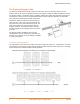
Allow a minimum of 1.9 cm (0.75 inches) between the roof and the bottom of the microinverter.
Allow 1.3 cm (0.50 inches) between the back of the PV module and the top of the microinverter.
You must install the M250 under the module, out of rain and sun.
Do not mount the microinverter in a position that allows long-term exposure to direct sunlight or in a
vertical orientation that allows water to collect in the DC connector recess.
Installing the microinverter black side up or vertically, with the DC connectors facing up, is not
permitted.
Racking Compatibility
The M250 Microinverter and Engage Cabling are compatible with a variety of racking systems. For a list
of approved PV racking types, refer to the Racking Compatibility document at
(http://www.enphase.com/support).
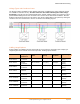
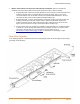
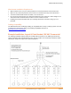
Example Installation: Layout & Parts Needed, 208 VAC Commercial
The following installation diagram shows an example with five branches. The 208V layout shows five
center-fed branches with 24 microinverters each. The PV modules are in landscape orientation. Tables
following the diagram list required and optional equipment.