
Component Guide

M250 Installation Planning
2013 Enphase Energy Inc. All rights reserved. July 2013
5
Planning for Cable Lengths and Type
The Engage Cable is flexible enough to adapt to almost any solar design. To determine the length and
cable type that you need, take into account the following considerations:
Calculate the number of Enphase Microinverters to be installed on the AC branch. Be certain to
allocate the correct number of connectors, including extra connectors for gaps and turns.
Account for any additional length required to reach from the AC branch circuit junction box to
the first microinverter. If greater than half a connector cable interval is needed, it may be necessary
to include one (or more) unused connectors in order to span this distance. Unused connectors must
be covered with Enphase sealing caps.
Plan to minimize the number of unused connectors with three-phase systems. If cable connectors are
left unused on a three-phase system, it creates a phase imbalance on the branch circuit. If multiple
cable connectors are skipped over multiple branch circuits, the imbalance can multiply.
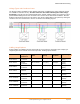
You can avoid skipping Engage Cable connectors with the use of Engage Couplers. For instance,
use the Engage Coupler to connect two Engage Cables or to connect Engage Cable to field cable.
There are many possible scenarios for each type of connection, but they generally fall into four
categories:
Engage Cable to Engage Cable:
1. Make use of leftover lengths of Engage Cable
2. Transition between portrait and landscape Engage Cable
Engage Cable to Field Cable (#12 TC-ER):
3. Transition between sub-arrays on the same circuit
4. Create wiring extensions for Engage Cable
NOTE: The Engage Coupler only supports #12 TC-ER, which may not be sufficient for
homerun wiring. Enphase Energy recommends maintaining less than 2% voltage drop
across all wiring.
In situations where you cannot use an Engage Coupler, you can use an electrical junction box to
transition between cable types.
You must account for all lengths of cable when calculating total VRise. Refer to the following
documents (at http://www.enphase.com/support) for more information on the Engage Coupler and to
maintain AC VRise at less than 2%:
o Applications of the Engage Coupler
o Circuit Calculations for the M250 Microinverter
o Calculating AC Line Voltage Drop for M250 Microinverters with Engage Cables
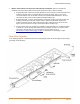
Additional length required to reach from one row of PV modules to the next. If the PV modules
are laid out in multiple rows, plan for any additional cable needed to cover the distance from one row
to the next.
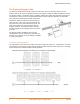
Bend radius. When planning cabling turns or loops, you must account for a minimum bend radius of
4.75 inches (12 cm).
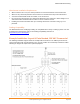
Multiple sub-arrays. Often, the AC branch circuit may be composed of several smaller sub-arrays
across more than one roof plane. In this case, cut the cable to service each smaller array, and
connect the sub-arrays using appropriately rated runs of conduit. Accomplish the transition from cable
to conduit by using an outdoor rated junction box, as required by the NEC and local code. You must
cover unused connectors with Enphase sealing caps.