
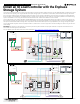
IQ Load Controller Installation
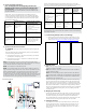

A ) Wire the low voltage connections of the Contactors
1) Connect the wire from A1 of the 2 contactors together via a wago
nut provided to Coil/Control Terminals 2 of the feed through header.
2) Ensure the A2 terminal of the 2 contactors is connected to the
negative of the power supply via a wago nut. The product comes
with this connection pre-wired.
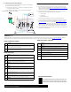
Low voltage contactor wiring diagram for PV shedding
B ) Complete the Power Supply connections
Refer the PV shedding wiring diagram on the rst page of the document
for the power supply wiring.
1) Connect the positive output of the power supply to the rst terminal
of the feed through header via a wago nut.
2) Ensure the negative output of the power supply has been connected
to the A2 of the 2 contactors via a wago nut.
3) Connect the neutral input of the power supply to the neutral neutral
terminal block. Connect the neutral block to the neutral bar on the
backed up panel.
4) Connect the line input of the power supply to a single pole on the
back up panel.
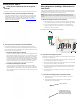
C ) Connect the feed through headers to IQ System Controller
1) Tighten the screws on the top (torque 0.22Nm to 0.25Nm) to
secure the wires.
2) Connect the feed through header to the correct IQ System
Controller aux contact terminals.
2. Tighten these screws to
hold the feed through header
in place once its inserted into
the auxiliary contact terminals
1. Insert wires here
2) Use Enphase Installer App to Go On-Grid:
On the ‘Live Status’ screen, toggle back the ‘Go Off-Grid’ toggle
switch to get the system back on-grid. You should see contactors’
contacts closed i.e., pushed down. Use a voltmeter to conrm that
there is voltage present on the load side (T1 / T3) contacts of the IQ
Load Controller.
B ) Post System Commissioning Steps: Functional Validation
Perform the following tests to ensure that the IQ Load Controller is
functioning as intended. The below mentioned tests are assuming the
kit is used for load control with basic mode setting. Similar tests can be
performed for PV controlling kits too.
1) Use Enphase Installer App to Go Off-Grid:
Go to the ‘Live Status’ screen. Use the ‘Go Off-Grid’ toggle switch to
get the system off-grid. When you do this, You should hear a sound
of the IQ System Controller’s Microgrid Interconnect Device (MID)
relay opening and see the contactors’ contacts opened i.e., pushed
up. Use the voltmeter to test the load side voltage and check that it
shows a 0V reading. This means that load control feature has been
successfully congured. Please note that it can take up to 40-60
seconds for the system to go off-grid and the MID to open.
Wiring Diagram for shedding 2 PV branches via
load control
If the IQ Load Controller is to be used for PV shedding, please apply the PV
shedding wiring label (provided with this QIG) on top of the load shedding
wiring diagram in the label on the inner door of the box.
NOTE: A single contactor can be used for shedding PV branch circuits
connected to a 40A over-current protection device with 32A continuous
current.
A ) Validation of Auxiliary contacts using Enphase Installer App
Go to the ‘Live Status Screen’ in step 7 of system commissioning for
validating the auxiliary contact connection. Follow the workow and
check that the system is behaving as expected. For more details,
please refer to the technical brief( available at: https://enphase.com/
installers/storage/load-control ).
INSTALLATION - PART 3
Testing the IQ Load Controller with the IQ System
Controller
Once the complete circuit has been wired, perform the below checks to
1