
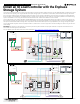
IQ Load Controller Installation
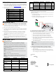

Perform the following tests to ensure that the AC wiring is connected
correctly. The below mentioned tests are assuming the kit is used for load
control. Similar tests can be performed for PV controlling kits too.
NOTE: If only using 1 contactor, you may disconnect the 24V control wiring
connected at the A1 terminal of the 2nd contactor. Remove unused wiring
from Wago connector.
Test Expected
Observation
What does the
observation
mean?
Possible cause
for not seeing
the expected
observation
1. Open the breaker
connected to the power
supply input.
2. Use voltmeter to test
the terminals of the
contactor.
3. Close the load
breaker.
The supply side of the
contactor should have
240V, load side should
have 0V
Contactor has been
correctly congured
Check L1, L2 line
connections.
Close the breaker
connected to the
power supply input
You should see
240Vac on both
sides. Armature
pin is sucked in.
Load is
successfully
connected and
operating.
Ensure power
supply wiring is as
described in step B
E ) Connect the AC lines of the Contactors
* WARNING! Deenergize all power wiring to the power supply and
contactors
Once the above test has successfully been performed, complete the
circuit by following the below steps
1) Connect the 2 wires from L1 & L3 of the contactor(s) to a double
pole breaker on the backup panel.
2) Connect the 2 wires from T1 & T3 of the contactors to the loads
that are to be controlled.
NOTE: Ensure that there is uniform current on the 2 outer poles of the
contactor. If a contactor is being used to shed 2 single pole 120V loads, do
ensure that both loads have similar power requirements.
NOTE: The AC output is not bonded to ground.
NOTE: The IQ Load Controller can also be used for shedding 4 loads run-
ning at 120Vac. If being used for such a use case it is important to ensure
that the individual loads are connected on the outer poles of the contac-
tors. Whenever possible, try to balance the current on the 2 poles of a
contactor. To do this, connect the 2 loads with similar current requirements
on the same contactor. This will prevent unequal wearing of the 2 poles of
the contactors, thus ensuring a longer service life for the contactor.
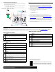
Contactor wiring diagram
F ) Commissioning Auxiliary Contacts via Installer App
1) Please refer the load control technical brief for details on using
the Installer App for commissioning the auxiliary contacts(avail-
able at: https://enphase.com/installers/storage/load-control).
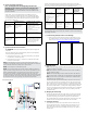
Test Expected Observation Possible cause for not seeing
the expected observation
Close the sub panel
breaker to which
the power supply is
connected.
The armature of the
contactor is closed
and the circuit is
complete.
Check the auxiliary contact
connections to make sure each
terminal is correctly
wired to the control power supply
output and the
coil of the intended contactor.
Test the line and neutral
wires connected to the
power supply
Voltage readings should be
120V. LED will illuminate
blue when 120V is applied.
Incorrect wiring to the backup
panel neutral bar and single pole
breaker
Observe the voltage
between the A1 and
A2 terminals of the
contactor
Voltage reading should
be 24V
Check the connections to the IQ
System Controller dry contact via
the feed through headers. Also,
check the conductors are fully
seeded in the wago nut.
D ) Test the Low Voltage Connections
NOTE: For the purpose of the low voltage wiring connections test
described next, please ensure you connect the feed-through headers
to the NC contacts. Post completion of this test, for the actual system
commissioning, you may choose either NC or NO ports available on the
IQ System Controller.
At this point, you have completed all the low voltage wiring con-
nections. Conduct the following test to ensure everything has been
correctly wired so far. Please make sure you perform this test before
you complete the wiring of the AC lines and commission the system
via Enphase Installer App.
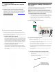
G ) Grounding the kit
NOTE: These grounding instructions are common to both use cases, load
shedding as well as PV shedding.
NOTE: The conductor used to connect to the Ground Terminal Block
must be at least 10 AWG
NOTE: If the conduit ttings require a GND connection, the GND con-
ductor used shall be 10 AWG and must originate from the GND splice.
NOTE: The Terminals on the GND Terminal block are suitable for the
connection of one conductor only.
The kit comes with a ground terminal block. We recommend having
as many ground wires from the backup panel to the ground terminal
block as the number of live wires owing in. If 2 loads are being shed,
then 3 ground wires must be brought in from the backup panel ground
bar( 2 for the load breakers, 1 for the power supply breaker). We also
recommend grounding the loads directly. Depending on the jurisdiction
in which this installation is being done, you may need to ground the
conduits as well.
H ) Managing the neutral wiring
According to the NEC code, the neutral wires must also pass through
the assembly(in this case, the IQ Load Controller) through which the
live wires are passing. The kit comes with a pre-mounted neutral
terminal block that can be used for landing the neutral wires from the
neutral bar on the backup panel and the wires from the loads.
I ) Securing the enclosure
The product comes with a zip tie provided in the kit. Please use the
same to lock the enclosure. The product does not contain any user
serviceable parts. Hence, it is essential to lock the enclosure. The
door must only be opened by a qualied personnel for any repair or
maintenance.