
IQ Load Controller Installation

B ) Complete the Power Supply connections
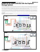
Refer the power supply wiring in the diagram provided on the rst page.
1) Connect the positive output of the power supply to Terminal 1 and
Terminal 3 of the feed through header via a wago nut.
2 ) Ensure the negative output of the power supply has been
connected to the A2 of the two contactors via a wago nut.
3 ) Connect the neutral input of the power supply to the neutral
terminal block. Connect the neutral terminal block to the neutral
bar on the backed up panel.
4 ) Connect the line input of the power supply to a single pole breaker
on the backed up panel.
NOTE: For wiring connections to the IQ System Controller, a 18-16AWG
wire is required.
NOTE: The power supply has a overload protection at 160% of the rated
power.
C ) Connect the feed through headers to IQ System Controller
1) Tighten the screws on the top (torque 0.22Nm to 0.25Nm) to
secure the wires.
2 ) Connect the feed through header to the correct IQ System Con-
troller aux contact terminals. We recommend using NO contacts
for PV shedding and NC for load shedding.
PREPARATION
A ) Download the Enphase Installer App version 3.X mobile app and open it
to log on to your Enphase App account. You will require this application
to commission and program IQ System Controller to work with the load
control box. To download, go to enphase.com/toolkit.
B ) If you have ordered the IQ load control box, check the package for the
following items:
INSTALLATION - PART 2
Wiring Instructions
NOTE: Electrical Shock Hazard. This work should be completed by a
trained electrician. Ensure all wiring is denergized prior to installation.
NOTE: The below instructions show the wiring for controlling 2 loads via
the IQ System Controller’s auxiliary contacts. Each load can be controlled
independently. Similar instructions for controlling PV are detailed towards
the end of this document.
NOTE: When used for load shedding, Use the IQ Load Controller for
controlling dedicated loads only.
NOTE: The contactor is rated for 36A resistive current and 25A Induc-
tive/3HP motor rating.
NOTE: Use AWG, 75º C copper conductors only.
NOTE: We provide a 18AWG 600V TEW wire with the product. If local
jurisdictions require a MTW or any other rated wire, please arrange
accordingly.
1
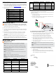
Sr No Item Quantity
1 IQ Load Controller Box 1
2 Din Rail 1
3 36A Contactor 2
4 Power Supply 1
5 Ground Terminal Block 1
6 Neutral Terminal Block 1
7 Din Rail End Clips 2
8 Splicing Connectors(Wago Nut) 2
9 18 AWG wire spool 1
10 Feed Through Headers 1
11 Installation Reference Sheet 1
INSTALLATION - PART 1
Choose a location for installing the IQ Load Controller
A ) Install the IQ Load Controller in a readily accessible location. Install it as
close to the IQ System Controller as feasible.
B ) Mount the IQ Load Controller on a vertical surface.
C ) The product comes with the negative of the power supply connected to
the A2 terminal of the 2 contactors via a wago nut. Ensure this wiring is
rmly in place.
D) We recommend a maximum diameter of 1.5 inches for any conduit
installed on the enclosure. Hubs must be connected to the conduit
before being connected to the enclosure. Conduit used must be
watertight.
E) Branch circuit protection is required using either DIVQ Breakers or Class
listed fuses. The breakers/fuses must be rated for 45A for the line
power terminals connected to the contactor, and 15A for power supply
input terminals.
1
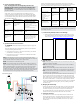
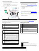
Low voltage contactor wiring diagram
2. Tighten these
screws to hold the
feed through head-
er in place once its
inserted into the
auxiliary contact
terminals.
1. Insert wires
here
Feed Through Header
Connection Type Torque(Nm) Wire Gauge
Contactor
Line/load power terminals 2.5Nm(22 Lb-in) 14-8AWG
Contactor A1/A2 control
terminals
1.2Nm(11Lb-in) 18-16AWG
Power Supply
120V L - N input terminals 0.34Nm(3Lb-in) 14AWG (10A breaker)
14AWG(15A breaker)
12AWG(20A breaker)
24V V+ / V- output
terminals
0.497Nm(4.46Lb-in) 18-16AWG
Ground bar terminal block 1.5Nm(13.3Lb-in) 24-6AWG
Neutral terminal block 1.5Nm(13.3Lb-in) 24-6AWG
A ) Wire the Control/Coil Terminals of the Contactors
Each feed through header has 4 terminal blocks.
For eaton contactors, A1, A2 are at the left of the contactor, whereas for
ABB, they are at the top.
1) Connect the wire from A1 of the left contactor #1 to Terminal 2 of
the feed through header.
2) Similarly connect the wire from A1 of the right contactor #2 to the
Terminal 4 of the feed through header.
EP-NA-LK02-040 Voltage Rating Current Rating OCPD
Load/PV
circuits
Dedicated load circuits 240/120VAC,
60Hz
36A Resistive, 25A
Inductive/3HP
45A
Branch circuit supplying
more than one load
240/120VAC,
60Hz
32A Resistive, 25A
Inductive/3HP
40A
PV circuits 240VAC, 60Hz 32A 40A
Power
supply
DC Power supply input 120VAC, 60Hz 12A 15A
DC Power supply output 24VDC 1.5A N/A