
User Manual


Planning for a Three-Phase IQ Microinverter System – North America
© 2017 Enphase Energy Inc. All rights reserved. September 20, 2017
12
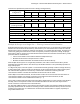
Transformer Specification (Table of Various Voltage Configurations)
Utility voltage
configurations
Nominal voltages between the lines and neutral/ground
L1 to L2
L2 to L3
L3 to L1
L1 to N/G
L2 to N/G
L3 to N/G
208Y/120V
208
208
208
120
120
120
No transformer would be specified for interconnection
480Y/277V
480
480
480
277
277
277
Specify a 480 delta:208Y/120V transformer or 480 delta:240 high-leg delta transformer
480 delta
(*corner grounded)
480
480
480
-
-
-
Specify a 480 delta:208Y/120V transformer or 480 delta:240 high-leg delta transformer
240 delta
240
240
240
-
-
-
Install a 240V to 120/240V auto-transformer for powering the Envoy (Hammond 170 “Auto”)
240 high-leg delta
240
240
240
120
120
208
No transformer would be required for interconnection of IQ System
600Y/347V
600
600
600
347
347
347
Specify a 600 delta:208Y/120V transformer or 600 delta:240 high-leg delta transformer
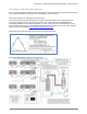
Multiple IQ Envoys on a Single Site — Filtering Communication Domains
Enphase IQ Microinverter systems use power line communications (PLC) to communicate module level data
between the microinverters and the IQ Envoy. Each IQ Envoy can communicate with a maximum of 600 IQ
Microinverters. The PLC signal is at 110kHz in an IQ System. In a commercial scale system, the IQ Envoy is
continuously polling the microinverters for their recent power production, temperature, voltage, amperage,
and frequency data. To ensure good communication between the IQ microinverters and the IQ Envoy, install
power line filters or transformers to:
• Prevent cross-domain communications between multiple IQ Envoys.
• Minimize electrical noise at frequencies near 110kHz.
• Minimize the distances between the IQ Microinverters and the IQ Envoys.
When multiple IQ Envoys are on a single utility transformer, use a filter to isolate each IQ Envoy and its
associated microinverters from the other IQ Envoys and IQ Microinverters. This is particularly important for
large-scale projects.
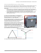
In a large-scale project, each sub-system or communication domain generally consists of a single IQ Envoy,
a single panel board, a power line filter, and the branch circuits off that panel board. A filter prevents power-
line communication signals from one IQ Envoy communication domain from interfering with other
communication domains. The filter also eliminates electrical noise from site loads.
With multiple communication domains, the total number of filters can be one less than the total number of
communication domains. For example, if all other communication domains have filters, the last
communication domain can be installed without a filter (n – 1).
If the system contains fewer than 600 microinverters with a single IQ Envoy on-site (a single communication
domain), a filter is not required to isolate communication domains from each other, but may be used to
ensure a clean PLC environment free of electrical noise.
For sites with multiple IQ Envoys, the conductors and conduits of each communication domain must be kept
physically separated from the conductors and wiring of other communications domains by at least 12 inches.
Coupling of the signals can occur between the conductors and conduits when run together, especially on
long conduit and wire runs.