
Component Guide


Planning an Ensemble Technology System – North America
19 © 2020 Enphase Energy Inc. All rights reserved. December 8, 2020
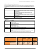
Key Planning Considerations
To ensure optimal wireless and power line communication between Ensemble system products and cleanest
installation, consider the following:
1. Identify a suitable environment for temperature, enclosure ratings, and wall area, for secure mounting of the
weight of the required Encharge storage system and Enpower smart switch units.
2. For wireless communications between the Envoy, Encharge storage system, and Enpower smart switch, the
best practice is to have a line-of-sight between them.
3. For power line communications, the best practice is to have the Envoy located closest to PV branch circuit
collection, for example in an IQ Combiner or near/in an off-the shelf PV combiner.
4. Determine the electrical interconnection points and required breakers for Enpower smart switch, Encharge
storage system circuit, PV combiner branch circuits, and the Envoy.
5. Ensure that the Envoy with both production and consumption CTs can be installed at the site.
6. Size conductors properly for ampacity and voltage regulation given conductor lengths.
7. Identify the location the PV system disconnect for rapid shutdown initiation and labeling.
8. Always ensure that the Envoy is connected to the internet via a Wi-Fi or ethernet connection. Note that the
cellular modem is provided as a backup connection for internet connectivity.
The following sections detail each of these considerations:
Physical Installation Considerations
1. For all products, always follow the instructions in the Enphase installation manuals.
2. Following local standards, choose a well-ventilated location where the ambient temperature and humidity
are within equipment specifications, preferably out of direct sunlight. The Encharge storage system battery
does not require additional ventilation as Lithium Iron Phosphate (LFP) chemistry used in battery cells does
not off-gas.
3. Ensure that the mounting location can sustain the weight of the equipment, mounting equipment, and
accessory equipment.
4. Plan the mounting location of Encharge:
• Minimum distance between Encharge units shall be 6 inches.
• Indoors: at least 15 cm (6 inches) off the ground and 15 cm (6 inches) from the ceiling.
• Outdoors: at least 15 cm (6 inches) off the ground.
• If mounted in the path of a motor vehicle, we recommend a 91cm (36 inches) minimum mounting
height
5. Plan the mounting location of Enpower:
• Indoors: at least 15 cm (6 inches) off the ground and 15 cm (6 inches) from the ceiling.
• Outdoors: at least 91cm (3 feet) off the ground.
• Indoors: at least 15 cm (6 inches) off the ground and 15 cm (6 inches) from the ceiling.
• Outdoors: at least 15 cm (6 inches) off the ground.
• If mounted in the path of a motor vehicle, we recommend a 91cm (36 inches) minimum mounting
height
6. Ensure that there are no pipes or electrical wires where you plan to drill.
7. Plan to maintain at least 90 cm (three feet) of clearance in front of Ensemble technology equipment for
working space.
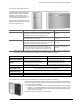
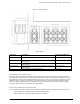
8. Consider the dimensions of the Ensemble equipment, easy access, height, and length of system conductors
and conduit requirements between products and the system interconnection location when selecting the
location of equipment. The recommended minimum spacing is shown in the following figure and table.
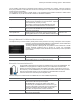
Conduit options are as follows:
• Enpower smart switch – Main supply conductors may enter Enpower smart switch from the bottom
or from the bottom-left side. Backup load conductors may enter Enpower smart switch from the
bottom or bottom-right side. Encharge storage system and PV combiner and generator conductors
may enter from the bottom, bottom-left or bottom-right sides.
• Encharge storage system – Conduit may enter from the top right or top left of the Encharge storage
system at the pre-defined knockout locations.
• IQ Combiner series – Conduit may enter at the bottom and sides or rear entry below the busbar
assembly.
9. Do not block vents.