
Component Guide

Planning an Ensemble Technology System – North America
13 © 2020 Enphase Energy Inc. All rights reserved. December 8, 2020
Load Breaker Installed in the Enpower Smart Switch
If there is an existing service equipment such as an existing fusible disconnect on the line-side of Enpower, a main
breaker may not be required on the line-side input of Enpower smart switch. However, a load breaker may still be
required. Size the load breaker with the same rating as the system over current protection device for the whole-home
(main panel) backup configuration. For example, if there is an existing 200 A meter disconnect combo feeding a main
lug panel board, Enpower smart switch would be installed with a 200 A rated Eaton CSR2200N (Enphase SKU: BRK-
200A-2P-240V) as a load breaker inside Enpower smart switch.
Main Breaker Installed in the Enpower Smart Switch
For the whole-home (main panel) backup configuration, if the service rating is less than 200 A, a load breaker may not
be required. For example, a 100 A service has DER over current protection totaling less than 100A. In this case,
Enpower smart switch would be installed with a 100 A rated Eaton CSR2100N (BRK-100A-2P-240V) as a main breaker
on the line-side of the main load panel. Ensure that the sum of load and DER breakers does not exceed 200 A rating
of the busbar and Enpower smart switch load conductors are rated appropriately.
Enpower Smart Switch Without Main or Load Breakers Installed
When Enpower smart switch is installed on the load side of the service equipment disconnect means, main and load
breakers may not need to be installed in the Enpower. For example, an Enpower smart switch is installed with total of
40 A of DER over current protection and that is back feeding a 200 A main breaker load center. In this case, it necessary
to install main or load breakers in the Enpower smart switch. Ensure that the sum of the load and DER over current
protection is less than 200 A and that conductors are sized to comply with 2017 NEC 705.12(B)(2)(1).
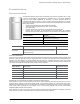
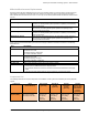
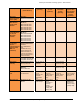
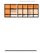
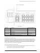
Encharge Storage System, IQ Combiner or Generator (future) Breakers
When connecting the Encharge storage system, IQ Combiner, or generator to the Enpower smart switch, use one of
the following circuit breakers depending on system requirements.
Model Number
Description
Shipment Contents
BRK-80A-2P-240V
Circuit breaker, 2-pole, 80A, 10kAIC, BR280 for Enpower
One box of one unit
BRK-60A-2P-240V
Circuit breaker, 2-pole, 60A, 10kAIC, BR260 for Enpower
One box of one unit
BRK-40A-2P-240V
Circuit breaker, 2-pole, 40A, 10kAIC, BR240B for Enpower
One box of one unit
BRK-30A-2P-240V
Circuit breaker, 2-pole, 30A, 10kAIC, BR230B for Enpower
One box of one unit
BRK-20A-2P-240V-B
Circuit breaker, 2-pole, 20A, 10kAIC, BR220B for Enpower
One box of one unit
Encharge and generator breakers may require a BRHDK125 hold down kit in accordance with 408.36(D) as referenced
in NEC 710.15(E). This hold down is not required for the IQ Combiner circuits with IQ 6 / IQ 7 series microinverters
since these inverters are still interactive inverters and are permitted to omit the additional fastener 2017 NEC
705.12(B)(5). This aligns with the AC coupled multimode system diagram, Figure 1, in 2017 NEC 690.1(b), which shows
both an interactive and multimode inverter. Encharge storage system includes the multimode inverters forming an
intentional local EPS island, and IQ 6 / IQ 7 series microinverters are utility-interactive inverters.
Generator Interface
The Enpower smart switch includes a 60 A generator connection for qualified generators (reserved for future use). This
document does not address this function, as the software functionality is not yet released. The Enpower smart switch
does not support integration with third-party automatic transfer switches (ATS) for the interconnection of generators.
Third-party transfer switches and unqualified generators may be connected on the load side of the Enpower smart
switch in compliance with NEC 705.2, and require isolating the Enphase DER equipment from the electrical system
powered by unqualified generators. Such third-party transfer switches and accompanying generators cannot operate
at the same time as Encharge storage systems and charge them.
Note that M-Series, microinverter-based Ensemble systems, when used with a generator, require all PV to be wired via
an external contactor. The contactor’s coil must be connected to Line 2 through the control terminals of the Envoy-S
Metered. This is similar to how the Envoy-S Metered is used with M-Series microinverters for Power Export Limiting in
the case of customer self-supply. Details can be seen in the Secondary Protection for Customer Self Supply Tech Brief.