
Install Manual
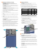

Vertical +5° inclination -5° inclination
430 mm
775 mm
188mm
IQ
TM
Battery 3T — single-width bracket
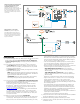
A ) Place the wall-mount bracket on the wall so that the mounting holes of the
bracket align with the center of the stud.
* WARNING! Risk of injury and equipment damage. Use the unit mounting
holes only to mount the base unit of IQ
TM
Battery to the wall mount. Do not
use the unit mounting holes to secure the bracket to the wall.
B ) Use a level to keep the bottom of the wall-mount bracket level.
C ) Use #20(5/16”) screws (or masonry attachments for masonry) to attach
the bracket using one screw and washer for each slot (9.2mm/0.36”). Use
minimum of three screws in each mounting bracket. Tighten all screws to
manufacturer’s specied torque values.
D ) Verify that the wall-mount bracket is solidly attached to the wall.
* WARNING! Risk of injury and equipment damage. Do not mount an
IQ
TM
Battery 3T on a bracket that is not properly mounted.
E ) If installing additional batteries, install adjacent wall-mount brackets, as
needed. Be sure to align the mounting holes in the wall-mount bracket to
the center of the wall stud. You may install another row of brackets above
the one already installed. Maintain at least 15 cm (six inches) vertical
clearance between rows and and 2.54 cm (1 inch) horizontal clearance
between units of IQ
TM
Battery 3T installations, and ensure that the wall can
support the structural load (weight) of the installation.
* WARNING! Risk of injury and equipment damage. Do not install more
than three IQ
TM
Battery 3T units per 20A branch circuit.
4
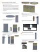
D ) The screws on the area below the red dotted rectangle would be
utilized in the next steps.
E ) Verify that the wall-mount bracket is solidly attached to the wall.
F ) Place the bottom wall-mount bracket below the middle bracket
aligning the holes and edges as shown in the image below:
G ) Use three number of #20(5/16”) screws and utilize three wall mount
slots that are common between middle and bottom wall-mount
brackets to attach bottom wall mount bracket on wall.
H ) Place the top wall-mount bracket sitting on top of middle wall-mount
bracket as shown in the image below:
I ) Use six number of #20(5/16”) screws and utilize six wall mount slots
to attach top wall mount bracket on the wall.
* WARNING! Risk of injury and equipment damage. Do not mount IQ
TM
Battery 10T batteries on a bracket that is not properly mounted.
J ) If installing additional batteries, install adjacent wall-mount brackets,
as needed. Be sure to align the mounting holes in the wall-mount
bracket to the center of the wall stud. You may install another row of
brackets above the one already installed.
Maintain at least 15 cm (six inches) vertical clearance between rows
and and 15 cm (six inches) horizontal clearance between units of IQ
TM
Battery 10T installations, and ensure that the wall can support the
structural load (weight) of the installation.
* WARNING! Risk of injury and equipment damage. Do not install more
than one IQ
TM
Battery 10T unit per 20A branch circuit.
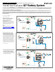
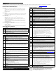
Allowable tilt from vertical for IQ
TM
Battery installation:
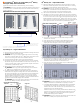
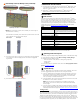
Single-width mounting bracket
Front view
Angle view
Wall mount
slots
Unit
mount
key
holes
478 mm
43 mm
418 mm
9.2 mm
* If the difference in atness is more than 2mm, recommend installing a
substructure like unistrut for better alignment of the units.
IQ Battery 10T
MOUNTING SURFACE
IQ Battery 3T
MOUNTING SURFACE
Mounting Surface Flatness (Across
the Installation width and height)
recommended to be within 2mm*
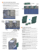
Install the IQ
TM
Battery 3T (single width) or IQ
TM
Battery
10T (triple width) wall mount bracket
Follow the instruction below for the bracket style you are installing.
* WARNING! Risk of injury and equipment damage. Attach the wall mount to
the wall so that it is no more than ve percent from vertical. See the following
image for reference:
IQ
TM
Battery 10T — triple-width bracket
A ) Place the middle wall-mount bracket on the wall so that the mounting
holes of the bracket align with the center of the stud, and the mounting
holes on the left and right align with the adjacent studs.
* WARNING! Risk of injury and equipment damage. Use the unit mounting
holes only to mount the base unit of IQ
TM
Battery to the wall mount. Do not
use the unit mounting holes to secure the bracket to the wall.
B ) Use a level to keep the bottom of the wall-mount bracket level.
C ) Use #20(5/16”) screws (or masonry attachments for masonry) to attach
the bracket using one screw and washer for each slot (9.2mm/0.36”). Use
a minimum of six screws in each middle mounting bracket (within the red
dotted rectangle) to support three IQ
TM
Battery units. There is an array of
slots so that you can choose those that allow you to mount the bracket on
studs. Tighten all screws to manufacturer’s specied torque values.
1270 mm
417 mm
417 mm
417 mm
61 mm
61 mm
284.5 mm
Triple-width mounting bracket
Wall mount
slots
Unit mount
key holes