
Install Manual

PREPARATION
A ) Inspect the packaging and the IQ
TM
Battery(ies) for damage, such as cracks,
dents, or leaking electrolyte. Do not install or use the IQ
TM
Battery(ies) if
it has been damaged in any way. If damaged, contact your distributor for
replacement.
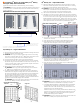
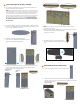
B ) Ensure that your kit includes the following
IQ
TM
Battery components:
•
The IQ
TM
Battery 10T includes three batteries and two interconnect
cable assemblies, an IQ
TM
Battery 10T triple-width cover, top, middle
and bottom mounting brackets.
•
The IQ
TM
Battery 3T includes one battery, and single-width cover with a
single-width mounting bracket.
NOTE: Check the “Energize By” label on the shipping box to verify that
the IQ
TM
Battery(ies) will be installed by the date shown. If the date has
passed, contact your distributor for next steps.
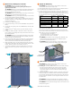
* WARNING: Risk of injury. Take care when lifting. The IQ
TM
Battery
unit is heavy (40.5 kg/ 89.3 lbs) and requires two persons to lift.
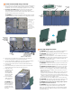
C ) Ensure you have the following required Enphase items for backup systems:
•
An Enphase IQ
TM
System Controller with microgrid interconnect device
(MID) functionality and an Enphase IQ Combiner.
•
The Enphase IQ
TM
Battery system requires an Internet connection
through the
IQ
TM
Gateway in the IQ Combiner. Failure to maintain
an Internet connection may have an impact on the warranty. See
enphase.com/warranty for full terms.
•
Wireless communications kit (COMMS-KIT-01) to be installed at the
IQ
TM
Gateway for communications with IQ
TM
Battery and IQ System
Controller. Includes USB cable for connection to
IQ
TM
Gateway / IQ
TM
Combiner and allows wireless communication with IQ
TM
Battery and
IQ
TM
System Controller.
D ) Make sure you also have the following required items:
•
Mounting location that is structurally suited to bear the weight of the
IQ
TM
Battery(ies). Total weight for the IQ
TM
Battery 3T, including the IQ
TM
Battery
base unit, cover and wall mount bracket, is 48.8 kg (107.6 lbs).
Total weight for the IQ
TM
Battery 10T, including the three IQ
TM
Battery
base units, cover, and wall mount bracket, is 152.1 kg (335.3 lbs).The
wall must contain blocked studs that can bear the battery weight or
can be of masonry or other suitable structure.
•
Tools: conduit (with ttings and tting tools), drill, 5/32 inch pilot bit
(or metric equivalent), screwdriver, socket wrench, torque wrench,
level, wire stripper, and stud nder if installing on studs.
•
Fasteners for wall mount bracket. Slots are 9.2mm (0.36”). Check with
a structural engineer and local standards for requirements:
Single-width bracket for IQ
TM
Battery 3T: A minimum of three
#20(5/16”) lag bolts or screws, 7.6 cm (3 inches) long (depending on
attachment wall).
Triple-width bracket for IQ
TM
Battery 10T: A minimum of fteen
#20(5/16”) lag bolts or screws, 7.6 cm (3 inches) long (depending on
attachment wall).
•
Washers for use between fastener heads and wall-mount bracket.
• Copper conductors: No. 14 - 8 AWG
(11mm/7/16 inch strip length)
copper conductors (rated at 75° C or 90° C) for terminals.
Conduit ttings: 1/2 inch or 3/4 inch (left side) hubs are required for
all installations, and NEMA Type 3R conduit ttings (hubs) are needed
when installing outdoors.
•
Over current protection: The overcurrent protection in IQ
TM
Battery is not
branch circuit overcurrent protection and cannot be relied upon for that
purpose. The branch circuit overcurrent protection is located in IQ System
Controller or, when combining , in a separate combiner. See the Enphase IQ
System Controller Quick Install Guide for more information.
•
Personal protective equipment (PPE) for handling lithium batteries as
required by local safety standards.
•
Protective gloves for protection against sharp edges.
E ) Verify that main service is 120/240 VAC, and not 208/120 VAC. IQ Batteries
cannot be installed where L1 to L2 measures 208 VAC.
F ) Note that the rated energy capacity of the battery is 3.36 kWh.
G ) Install the PV system and the IQ Combiner as directed by the Enphase
installation manuals.
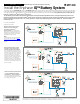
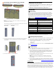
Self consumption, no IQ
TM
System
Controller. The preferred conguration
when adding battery storage and PV for
self-consumption in a grid-tied application
with no option for backup during outages.
PV and IQ
TM
Battery will not operate when
the grid is unavailable.
Partial home backup with main load panel
as service entrance and PV combiner
connected to subpanel. This is the
preferred connection conguration for
partial home backup using a subpanel when
the PV circuit breaker size is more than
80A. The space available in IQ
TM
System
Controller for combiner (solar) connection
is left vacant.
(optional)