
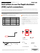
Enphase RSD Switch quick install guide

Functional tests
A ) Use the Enphase Installer App to check if the RSD is working as de-
sired. When the RSD is engaged (turned to OFF position) , all the relays
except the MID will be open. Only the MID relay will be closed. Hence
effectively isolating the home from the PV, battery and generator.
B ) In order to check if the RSD is functioning as required, open the ITK
and go to the IQ System Controller page.
C ) Turn the RSD rotary handle to OFF position.
D ) In the Enphase Installer App’s IQ System Controller page, click on
“View Live details”.
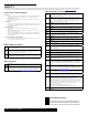
E ) In the view live details page, the relay status should be as shown in
Figure 6 below. The MID relay should be closed and all other relays
should be in open position.
F ) When RSD handle is shifted to ON position, the IQ System Controller
goes back into functioning normally as it was.
6
Figure 6: ITK checking of Relay status
Instructions for initiating Rapid Shut down and IQ
System Controller System shut down
Rapid shut down of the system can be initiated by turning the handle
of the RSD to the OFF position. With this one step the entire Enphase
system (PV arrays , IQ Battery, generators connected to IQ System
Controller) is shut down and the regulatory requirement for rapid shut
down are also met.
NOTE: For more details of the RSD switch options and wiring
instructions, please refer to IQ System Controller 2 QIG or the Enphase
Energy System design guide
8
Completetheinstallationbyafxingthelabels
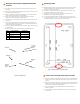
A ) In order to identify the Rapid shut down switch the following label (in
Figure 7) needs to be pasted at a distance of not more than 3ft (1m)
from the RSD, as mandated by the NEC code.
7
Figure 7: Label for identifying the RSD
Figure 8: Sticker for showing portions of PV array which will be shut down using RSD
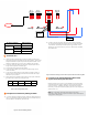
I/O - 1
(24V, 1A)
I/O - 2
(24V, 1A)
Gen - I/O
(24V, 1A)
NO1 NO2 NC1 NC2
NO3
RSD
NC3 NC4
AC Combiner PV/Storage Generator
B ) In order to earmark the parts of the array which will be shut down
by using the RSD the following sticker (Figure 8) needs to be pasted
in the location specied by the Authority having jurisdiction or at a
distance of not more than 3ft (1m) from from the RSD, as mandated
by the NEC code.
Dry Contact Terminals RSD Terminals to
be connected
NC3
Terminal 1 Terminal 1
Terminal 2 Terminal 2
NC4
Terminal 1 Terminal 3
Terminal 2 Terminal 4
Figure 5: Connecting wires from RSD and IQ System
MID EC1 L1 EC1 L2 NFT L1 NFT N
Closed Open Open Open Open
Cable Header
Assembly
(refer Fig 2a)
12 AWG
wires