
Technical Brief for Installation of Consumption Monitoring
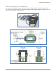
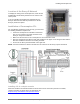
Table Of Contents
- Assessing a Site for Installation of Consumption Monitoring
- For North America and Latin America
- About the Enphase Envoy-S Metered
- About Consumption Monitoring
- Consumption Current Transformers
- Site Assessment Form
- Circuit Detail Form
- 200A Consumption CT Dimensions
- Location of the Envoy-S Metered
- Installation of Consumption CTs
- Installing CTs in a simple scenario
- Installing CTs in Eaton Service Panels / Solar Power Center
- Installing Multiple Conductors in a Single CT
- Installing Parallel Connected CTs for 400A Services and Crowded Service Panels
- Calculating Whether Multiple Conductors Fit Within a CT
- Example Calculations for a Service Panel
- Retrofitting the Electrical Service for CT Installation
- Extending the Consumption CT Conductors
- Net Consumption versus Total Consumption
- Monitoring with the Installer Toolkit Mobile App
- Troubleshooting
- Viewing Sites with Consumption Monitoring

Installing Consumption CTs
2016 Enphase Energy Inc. All rights reserved. January 2016
7
Two CTs on Line 2:
one at top of panel
one at bottom of panel
Two CTs on Line 1:
one at top of panel
one at bottom of panel
Installing Parallel Connected CTs for 400A Services and Crowded Service Panels
In many scenarios, it is difficult to install multiple conductors through a single CT, because some of the
conductors may enter from the bottom of the service panel and others enter from the top of the service
panel. Also, some service panels have 400A services that are provided by a set of two 200A conductors and
parallel-connected 200A circuit breakers. In those scenarios, it is possible to use a set of parallel-connected
consumption CTs to monitor the home’s consumption. Do this by installing two consumption CTs on each line
conductor and then parallel-connecting the output conductors at the Envoy-S CT wiring terminals or in a wire
connector prior to landing in the Envoy-S terminals.