
Technical Brief for Installation of Consumption Monitoring
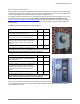
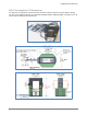
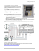
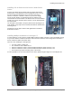
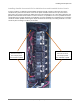
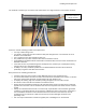
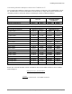
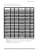
Table Of Contents
- Assessing a Site for Installation of Consumption Monitoring
- For North America and Latin America
- About the Enphase Envoy-S Metered
- About Consumption Monitoring
- Consumption Current Transformers
- Site Assessment Form
- Circuit Detail Form
- 200A Consumption CT Dimensions
- Location of the Envoy-S Metered
- Installation of Consumption CTs
- Installing CTs in a simple scenario
- Installing CTs in Eaton Service Panels / Solar Power Center
- Installing Multiple Conductors in a Single CT
- Installing Parallel Connected CTs for 400A Services and Crowded Service Panels
- Calculating Whether Multiple Conductors Fit Within a CT
- Example Calculations for a Service Panel
- Retrofitting the Electrical Service for CT Installation
- Extending the Consumption CT Conductors
- Net Consumption versus Total Consumption
- Monitoring with the Installer Toolkit Mobile App
- Troubleshooting
- Viewing Sites with Consumption Monitoring

Installing Consumption CTs
2016 Enphase Energy Inc. All rights reserved. January 2016
6
Installing CTs in Eaton Service Panels / Solar Power
Center
In many of the Eaton Service Panels and in the Eaton Solar Power
Center panels, it may appear that the consumptions CTs fit on one of
the service entrance conductors, but not on both of the service
entrance conductors or busbars. However, if you test the voltage
across the main breaker, you will find that the line conductors are
rotated inside the circuit breaker. This allows for the CTs to be installed
so that one is on the conductor above and one is on the bussing below
the main breaker.
You must place the breaker in the open position when attaching the CT
to the busbar. It may help to loosen the bolt that holds the busbar when
attaching the CT.
Install the CTs on the right conductor and right busbar in the Eaton
Solar Power Centers.
Installing Multiple Conductors in a Single CT
In some situations, you may need to install multiple conductors within a single CT. This is acceptable as long
as you ensure that the conductors terminate on the same line conductor, so the voltage at the terminals of
the two conductors will be 0V between them.
There are some challenges to this approach.
• It is easy to make a wiring error.
• The conductors must fit within the CT.
• All of the conductors on line 1 must be bundled and with the loads on the line 1 CT
• All of the conductors on line 2 must be bundled and with the loads on the line 2 CT.
• This method may require extending some of the circuits.
It is often possible to run all of the conductors in a service panel through a single set of consumption CTs.