
Technical Brief for Installation of Consumption Monitoring
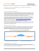
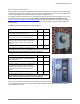
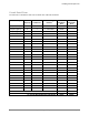
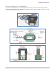
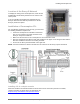
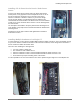
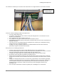
Table Of Contents
- Assessing a Site for Installation of Consumption Monitoring
- For North America and Latin America
- About the Enphase Envoy-S Metered
- About Consumption Monitoring
- Consumption Current Transformers
- Site Assessment Form
- Circuit Detail Form
- 200A Consumption CT Dimensions
- Location of the Envoy-S Metered
- Installation of Consumption CTs
- Installing CTs in a simple scenario
- Installing CTs in Eaton Service Panels / Solar Power Center
- Installing Multiple Conductors in a Single CT
- Installing Parallel Connected CTs for 400A Services and Crowded Service Panels
- Calculating Whether Multiple Conductors Fit Within a CT
- Example Calculations for a Service Panel
- Retrofitting the Electrical Service for CT Installation
- Extending the Consumption CT Conductors
- Net Consumption versus Total Consumption
- Monitoring with the Installer Toolkit Mobile App
- Troubleshooting
- Viewing Sites with Consumption Monitoring

Installing Consumption CTs
2016 Enphase Energy Inc. All rights reserved. January 2016
5
Location of the Envoy-S Metered
To simplify the wiring of the consumption CTs, locate the AC
Combiner Box and/or Envoy-S Metered at or near the main
service panel.
If you are installing the Enphase AC Combiner Box, the
Envoy-S Metered comes with the production CT and the
Envoy-S prewired for power.
Installation of Consumption CTs
For consumption monitoring to work correctly, you must meet
the following installation requirements:
• Attach the consumption CT installed on terminal IA
(line 1) to the same line as power terminal A of the
Envoy-S. Verify with a voltmeter.
• Make sure that the arrow on the consumption CT faces toward the loads.
• Wire the consumption CTs with the white wire installed on the upper row of wiring terminals and the
blue wire installed on the lower row of wiring terminals.
• Do not use the Envoy-S terminal block on the right side.
NOTE: You must install the CT wired to terminal IA on the same line as the Envoy-S power terminal A.
Installing CTs in a simple scenario
When the conductors or busbars between the main service meter and service panel are accessible,
complete the wiring as shown above as described in the
Enphase Envoy-S Installation and Operation Manual.