
Technical Brief for Installation of Consumption Monitoring
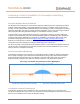
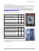
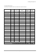
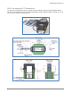
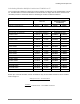
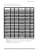
Table Of Contents
- Assessing a Site for Installation of Consumption Monitoring
- For North America and Latin America
- About the Enphase Envoy-S Metered
- About Consumption Monitoring
- Consumption Current Transformers
- Site Assessment Form
- Circuit Detail Form
- 200A Consumption CT Dimensions
- Location of the Envoy-S Metered
- Installation of Consumption CTs
- Installing CTs in a simple scenario
- Installing CTs in Eaton Service Panels / Solar Power Center
- Installing Multiple Conductors in a Single CT
- Installing Parallel Connected CTs for 400A Services and Crowded Service Panels
- Calculating Whether Multiple Conductors Fit Within a CT
- Example Calculations for a Service Panel
- Retrofitting the Electrical Service for CT Installation
- Extending the Consumption CT Conductors
- Net Consumption versus Total Consumption
- Monitoring with the Installer Toolkit Mobile App
- Troubleshooting
- Viewing Sites with Consumption Monitoring

Installing Consumption CTs
2016 Enphase Energy Inc. All rights reserved. January 2016
3
Circuit Detail Form
Use this form to calculate the total cross sectional area of all load conductors.
Circuit Description
Breaker
Ampacity
Line
Conductors
Conductor Type
and Size
L1 – Black
Conductor
Area
L2 – Red
Conductor
Area
Example (Oven)
50
1 and 2
2 - #6 THWN
0.0507in
2
0.0507in
2
Example (Lights 1)
20
1
1 - #12 THWN
0.0133in
2
Example (Lights 2)
20
2
1 - #12 THWN
0.0133in
2
Total
CT 60% Fill Rating (Maximum Fill Rating)
0.484in
2
0.484in
2