
Enphase IQ Microinverter System Planning Tech Brief
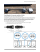
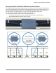
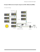
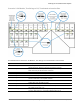
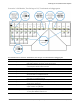
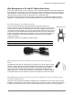
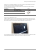
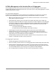
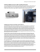
Table Of Contents
- Planning for an IQ Microinverter System
- IQ 6 and IQ 6+ Micros
- Q Cable and IQ Micro Accessories
- IQ System Design using the IQ Combiner
- IQ System Design with Q Aggregator
- Field Wireable Q Connectors and Raw Q Cable
- Splicing Q Cable and Raw Q Cable with Junction Boxes
- Example IQ Microinverter System Layouts and Bill of Materials (BOMs)
- Wire Management of AC and DC Cables Under Array
- AC Wire Management at the Junction Box or Q Aggregator
- Installing IQ Microinverters with Frame Mount Bracket
- Installing the Power Line Filter (Q-LCF-064-1)

Planning for an IQ Microinverter System
© 2017 Enphase Energy Inc. All rights reserved. July 28, 2017
12
Splicing Q Cable and Raw Q Cable with Junction Boxes
For complex installations that include multiple arrays, it is possible to use raw Q Cable (Q-12-RAW-300) to
service the arrays and branch circuits that do originate directly at the primary roof mounted junction box. In
the case that Field Wireable Q Connectors are not readily available, a small junction box may be used to
splice two sections of Q Cable together or may be used to splice Q Cable to raw Q Cable.
The raw Q Cable is available in 300m (938ft) cable rolls (Q-12-RAW-300).
You must terminate the raw Q Cable in one of the following manners:
• Into a junction box using a ½” service entrance (SE) strain reliefs or UF cable glands
• With a Field Wireable Q Connector (male or female)