
Enphase Ensemble Technology System Planning Tech Brief

Planning an Ensemble Technology System – North America
14 © 2019 Enphase Energy Inc. All rights reserved. December 17, 2019
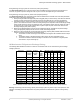
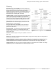
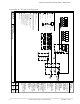
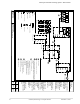
Appendix A – Single line diagrams
Wh
IQ Combiner 3CE
Encharge 10
Main Load Center
Wh
Genset
Energy Meter
Autotransformer
Current Transformer(CT)
Circuit breaker
PV Module
NO Contactor/Relay
Inverter
Battery module
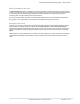
Enpower 200G with Main and Load Breaker.
Consumption CTs installation required.
Breaker configuration is application specific.
Optional Generator
Dependant on future software release.
Production CT includes all Line 1 conductors.
Encharge 3 Encharge 10 with NEMA 3R rating.
Enpower 200G
Encharge
AC Combiner
Auto Transformer
Generator
Envoy
Mobile
Connect
Wireless
Comms
IQ6 or IQ7 Micros
Encharge 3
Utility Meter
Optional Disconnect
Encharge continous power output shall comply
with 2017 NEC 690.10.
PV AC power output shall not exceed Encharge
Peak output power rating.
Additional Paneboard required to combine more
than (6) Encharge 3 base units connected to
Enpower 200G.
Fuse
Switch/Disconnect
PV rapid shutdown initiatiation device or AC disconnect may be
required per local codes. PV rapid shutdown can be initiated by
breakers in IQ Combiner, AC disconnect, or PV circuit breaker in
Enpower.
DWN BY:
NRC
DRAWING No:
NA-1AC-1PH
DRAWING Name:
Example: Whole Home Backup
REV:
1
CHK BY:
MR
SHEET:
1 of 1
DATE :
11/13/2019
SCALE:
NTS
This documentation
is provided for
recommendation
and suggestive
purposes to
demonstrate
Enphase solutions
and products in
end-use energy
project applications.
Drawing may not
represent all local
code and
jurisdiction
requirements.
Final design and
actual performance
of any solar and/or
storage energy
project as well as
complying with all
specifications,
installation
requirements and
local codes is the
responsibility of the
party this
information is
provided to.
Enphase is not
responsible for use
of the data provided
herein.
© Enphase
Energy 2019