
Enphase Ensemble Technology System Planning Tech Brief


Planning an Ensemble Technology System – North America
12 © 2019 Enphase Energy Inc. All rights reserved. December 17, 2019
Current Transformers (CTs)
It is critical that installers correctly configure the IQ Envoy, with the combined solar PV output passing through the
production CT. The production CT monitors only the PV output circuit(s) and must not have Encharge battery
circuit(s) installed on it. Install the Encharge battery circuit(s) on the load side of the production CTs on the correct
terminals in Enpower smart switch.
Installers may extend the consumption CT leads, but not the production CT leads. Therefore, it is best to locate the
IQ Envoy close to the microinverter output circuits and then extend consumption CT wires if necessary. Refer to the
IQ Envoy Installation and Operations Manual when installing and/or extending consumption CTs.
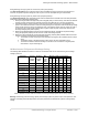
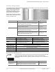
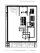
Enpower smart switch connections
The Enpower smart switch can accept a maximum of 64 A of continuous output current (maximum 80A breaker) of a
combined PV subpanel or IQ combiner (labeled AC Combiner). The busbar in the Enpower smart switch can accept a
maximum of an 80 A breaker for the IQ combiner over current protection.
The Enpower smart switch can accept a maximum of 64 A of rated output current (maximum 80A breaker) of
combined Encharge storage system circuits. The busbar in the Enpower smart switch can accept a maximum of an
80 A breaker for the Encharge storage system circuit over current protection. This equates to a maximum of twelve
Encharge 3 storage units or four Encharge 10 units per Enpower. Up to six Encharge 3 storage units or two
Encharge 10 units, equal to 32 A of rated output current, can be connected in series prior to landing on the Encharge
terminal in the Enpower smart switch and protected by a no higher than a 40 A over current protection breaker. If
more than six Encharge 3 storage systems (or more than two Encharge 10 storage systems) are to be connected to
Enpower smart switch, an external subpanel must be used to combine each circuit of up to 32 A of rated output
current Encharge storage system circuits. You should size conductors appropriately for the overcurrent protection
selected for the application.
Voltage Regulation Considerations
When the Encharge storage system is charging, it acts like a load and the voltage decreases at the terminals of the
battery based upon Ohm’s law and wire resistance. When the Encharge storage system is discharging to feed loads,
it behaves like a source, and the voltage increases at the terminals of the battery.
The voltage rise to voltage drop delta divided by the nominal voltage is roughly equivalent to voltage regulation. Since
the peak charge and discharge values for Encharge are the same value, voltage rise and voltage drop will be the
same value.
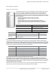
Voltage regulation in Ensemble is calculated as
𝑃𝑒𝑟𝑐𝑒𝑛𝑡'𝑉𝑅 =
2 ∙
|
𝑉
.
|
𝑉
/01
'
where:
𝑉
.
is the voltage change from 0 to max current out of Encharge, and
𝑉
/01
is the nominal RMS voltage.
Ensure that the Encharge storage system conductors are sized correctly for number of units on the circuit and voltage
regulation does not exceed 1% between the first Encharge storage system and Enpower smart switch.
Rapid Shutdown Considerations
Any Enphase IQ 7 and IQ 6 microinverter PV system disconnecting means is capable of meeting the requirements of
rapid shutdown initiation. When installing Enpower smart switch and Encharge storage system, the PV system
disconnecting means becomes the rapid shutdown initiator. The breakers in the IQ combiner can be used to initiate
rapid shutdown since it contains fewer than six breakers to shut down the entire system. Comply with local and
National Electric Code requirements for identification, grouping and labeling.