ENMET Corporation PO Box 979 Ann Arbor, MI 48106-0979 Instruction Manual Gas Sampling Unit DC Operation 80003-141 February 1999 MCN-248, 01/22/01 MCN-291, 10/21/03
Table of Contents 1.0 INTRODUCTION...................................................................................................................................................................................1 1.1 UNPACK .................................................................................................................................................................................................. 1 1.2 CHECK ORDER .........................................................................
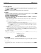
ENMET Corporation Gas Sampling Unit 1.0 Introduction The ENMET gas sampling unit is used in applications requiring air sample draw to a sensor. It is designed to be used in conjunction with ENMET sensor/transmitters. If used with other manufactures’ sensor/transmitters, contact your local ENMET representative or ENMET NOTE: All specifications stated in this manual may change without notice. 1.1 Unpack Unpack the Gas Sampling Unit and examine it for shipping damage.
ENMET Corporation Gas Sampling Unit 2.0 Specifications Power Requirement 10 - 30 V DC Suction Flow Rate 0.3 Liter/min. (adjustable after installation) Sampling distance 100 ft maximum Suction Pump Electromagnetic diaphragm pump Piping Material Polypropylene, non toxic vinyl tubing External Piping Connections Compress fitting for ¼ O.D. tubing Installation Method Wall mounting Dimensions 11(w) X 6.
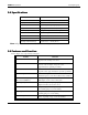
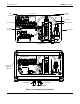
ENMET Corporation Gas Sampling Unit Power Terminals 10 – 30 VDC Flowmeter Valve Flowmeter 10 – 30 VDC Sample Pump Sensor Chamber Flow Sensor Internal View Enclosure NEMA-4X (Optional) Sample Inlet Exhaust Outlet External View Figure 1: Gas Sampling Unit Features 3
ENMET Corporation Gas Sampling Unit 4.0 Installation The Gas Sampling Unit needs to be level and as close to the area to be monitored as possible, to reduce transport time to the sensor/transmitter. • Refer to Figure 2 for mounting dimensional diagram. • Sensor/Transmitters can be located within the Gas Sampling Unit or remotely. Refer to Figures 3,4 and 5 • Inlet tubing must be compatible with the target gas. • Caution should be used to insure that fluids do not enter the inlet tubing.
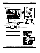
ENMET Corporation Gas Sampling Unit 12VDC in Terminal positions 1 & 3 Gas Sampling Unit Outlet Sensor Adapter ISA-M Clear Plastic Tubing Sensor use Teflon tape to seal Cord or Conduit 110 V AC Line Cord Sample from Remote Location Sensor Wiring Enclosure Using 12 VDC source ISA-M From: ISA-M terminal TB2-positions 7&8 To: Gas Sampling Unit terminal positions 1&3 12 VDC Out TB27: Positive 8: Ground View of Internal PCB in ISA-M Figure 4: Application, Remote Sensor, Motorized Sample Draw System 5
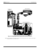
ENMET Corporation Gas Sampling Unit Sensor/Transmitter Model RX – 1G Control 24 VDC Gas Sampling Unit Figure 5: Wiring Diagram Gas Sampling Unit with RX-1G Control NOTE: On some installations, the 4-20mA signal may be wired through the flow switch, so that the 4-20mA signal is interrupted when low flow conditions occur.
ENMET Corporation Gas Sampling Unit 5.0 Operation The Gas Sampling Unit requires no calibration itself, however any sensor/transmitter or instrument associated with it does. Follow the instructions associated with the sensor/transmitter or instrument. To insure that the calibration is accurate with the sample draw system, you need to fill a sample bag with calibration gas. 5.1 Procedure for Sampling from Gas Bag • Refer to Figures 6,7 and 8 for filling gas bag and attaching to Gas Sampling Unit.
ENMET Corporation Gas Sampling Unit Inlet Port Outlet Port Outlet port without exhaust line requires a secondary gas bag to collect calibration gas to prevent it from escaping into environment Calibration Gas Bags Figure 7: Venting Calibration Gas to a Gas Bag Inlet Port Outlet Port Outlet Port with exhaust line to proper ventilation area does not require a secondary gas bag.
ENMET Corporation Gas Sampling Unit 6.0 Maintenance The flow rate of the sampling pump should be checked occasionally. The sampling pump has a diaphragm, which may ware out. Wear on the diaphragm has a direct influence of flow rate. If the flow rate decreases, and there is no restriction in the air line, the diaphragm may need replacing. There are two styles of diaphragm pump that have been used in the Gas Sampling Unit. See illustrations in sections 6.1 and 6.
ENMET Corporation 4. Remove diaphragm from armature by pulling it over the retaining screw. 5. Replace diaphragm. –Wet new diaphragm hole liberally with water. 6. Pop new diaphragm onto armature screw post. 7. Wet with water inside wall and lip of diaphragm. 8. Press diaphragm onto valve housing by pressing armature down.
ENMET Corporation Gas Sampling Unit 6.2 Pump Maintenance for Pump 04018-118 For the maintenance of ENMET part number 04018-118. Diaphragm Star Head Screw 2 places Pump Arm Check Valve Housing Mounting Screws 3 places Top View Side View Figure 10: 04018-118 Pump Features 6.2.1 Pump Diaphragm Replacement If the diaphragm becomes damaged or torn, it can be replaced. Replacement diaphragm ENMET part number 04018-117. Figure 11: Diaphragm Details Remove 2 star head screws and pump arm.
ENMET Corporation Gas Sampling Unit 6.2.2 Check Valve Housing Replacement If the check valve becomes damaged or to warn to operate correctly it can be replaced. Pump repair kit ENMET part number 04018-116. W ARNING: The check valve housing and associated gasket must be installed in the proper position for the pump to operate correctly. If they are installed improperly the pump will flow in the wrong direction.
ENMET Corporation Gas Sampling Unit 7.0 Warranty ENMET warrants new instruments to be free from defects in workmanship and material under normal use for a period of one year from date of shipment from ENMET. The warranty covers both parts and labor excluding instrument calibration and expendable parts such as calibration gas, filters, batteries, etc... Equipment believed to be defective should be returned to ENMET within the warranty period (transportation prepaid) for inspection.
ENMET Corporation Gas Sampling Unit Notes: 14
PO Box 979 680 Fairfield Court Ann Arbor, Michigan 48106-0979 734.761.1270 Fax 734.761.3220 Returning an Instrument for Repair ENMET instruments may be returned to the factory or any one of our Field Service Centers for regular repair service or calibration. The ENMET Repair Department and Field Service Centers also perform warranty service work.
Repair Return Form Mailing Address: ENMET Corporation PO Box 979 Ann Arbor, Michigan 48106 Phone Number: FAX Number: Shipping Address: ENMET Corporation Attn: Repair Department 680 Fairfield Court Ann Arbor, Michigan 48108 734.761.1270 734.761.