INSULATED METAL WALL PANEL INSTALLATION GUIDE May 31, 2012 Version 1.
TABLE OF CONTENTS Profiles………………………………………………………………………………………………………........ 2 Introduction Accountability Conditions Heavy Equipment……………………………………………………………………………………………. 3 Verifying the Structure/Alignment Panel Side Joints Vapor Barrier Sealants………………………………………………………………………………………………………….. 4 Field Applied Insulation Threaded Fasteners Strippable Film……………………………………………………………………………………………….. 5 Field Cutting Appearance General Installation Sequence………………………………………………………………………….
PROFILES Infinity Stucco Impression MesaLine VeeLine WaveLine ShadowLine INTRODUCTION Insulated metal panels (IMPs) are premier building products on the leading edge of innovation. The panels are formed by a continuously, foamed-in-place manufacturing process which binds interior and exterior steel facings to a polyisocyanurate, insulating core.
Englert does not warrant any product or material as meeting the ordinance, laws or regulations of any particular stated or local municipality, and Englert is not responsible for conformance to such ordinances, laws or regulations. Englert is not liable for damage or loss of materials at the jobsite. HEAVY EQUIPMENT Unloading the panel bundles will require a suitable fork lift or crane. Please refer to the Handling & Maintenance Guide for additional information.
It is the installer’s responsibility to ensure that the specified sealants are in good condition and applied in the proper manner. It is the designer’s responsibility to understand the project’s unique environmental and operating conditions and to specify the appropriate vapor control measures. Location of vapor barrier sealants must be addressed by a design professional. SEALANTS Before wall panels are installed, ensure that all applicable interior trim is sealed and installed per the project drawings.
and at the specified spacing. Reference the project’s installation drawings for the specified fasteners and spacing. For typical applications the panels are attached to the framing members with clips and screws concealed within the panel joint. In some cases the design loads will require backside attachment of the panels to the framing members in addition to the clips. At wall corners, framed openings and wall termination, the edges of the panels are attached to the framing member with thru-panel screws.
GENERAL INSTALLATION SEQUENCE 1. 2. 3. 4. 5. 6. 7. 8. 9. 10. Install and caulk the appropriate flashing/trims. Measure and cut the first panel Place and plumb the first panel Through-fasten the cut edge. Install clips and fasteners along the factory edge of the panel at the girt locations. Apply sealant pigtails. Field-caulk the second panel. Place and engage the second panel. Install clips and fasteners along the factory edge of the panel at the girt locations.
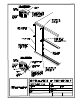
DETAILS The following section of this manual contains details which address the installation of insulated metal wall panels and their associated flashings. The details are generic, showing typical wall framing and flashing conditions. Because of the many variations of applications and construction conditions, these generic details may vary from the project’s actual conditions. Always reference the project’s installation drawings for the specified requirements.
Product of Englert, Inc. 1200 Amboy Avenue Perth Amboy, NJ 08861 (732) 826-8614 www.englertinc.