
Use and Care Manual


2.0ft.
18.0in.
3.0ft.
INSTALLATION
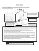
Approved Venting Method 3:InternalorExternalMasonryChimneySystem
10
ft.
Chimneylinercross‐sectional
area(LengthxWidth)must
be
nolargerthantwicethecross‐
sectionalareaofthefluecollar
(2x28.27in
2
=56.55in
2
). If
chimneylinerislargerthan
56.55in
2
,reliningwitha5.5”
or6.0”linerisrequired
The10‐3‐2Rule:Thechimneysystem
mustterminate3.0ft.abovethepoint
whereitscenterlinepassesthroughthe
roofANDthechimneymustterminate
2.0ft.aboveanypartofthedwelling
withina10ft.radiusofthechimney.
ChimneyConnector
(SingleorDoubleWall)
MasonryThimblewith
properclearanceto
combustibles
AshCleanoutsmust
haveanairtightsealto
preventweakdraft.
•
Followtheruleslistedaboveconcerningmaximumpermissiblefluelinersize;installingthisunitonmasonrychimneys
exceeding56.55in
2
incross‐sectionalareawillresultindecreaseddraft andthepotentialforpoorunitperformance.
•
Usethreesheetmetalscrewsateachsinglewallchimneyconnectorjoint(checkmanufacturer’s
recommendationswhendoublewallchimneyconnectorisused).
•
Drillthreeholesinthefluecollaroftheunitandattachthechimneyconnec tortotheunitusingsheetmetal
screws(holesshouldbepre‐drilledinfluecollarfromfactory).
•
Avoid numerous elbows and excessive horizontal runs as both will lead to poor draft and increased creosote
accumulation. Horizontal runs of chimney connector must never exceed 4.0 ft. and the overall length of the
chimneyconnectormustnotexceed8.0ft.withsinglewallblackconnector pipe. Ifnecessarytorunlongerth
an
8.0ft.ofchimneyconnectorpipe,double wallblackchimneyconnectorpipemustbeused.
•
Atightsealatthethimbleiscrucialforproperunitperformanceandtocreateasafeinstallation. Usetheproper
adapterdesignedforconnectingsingleordoublewallchimneyconnectortoamasonrythimble.
•
Haveexistingmasonrychimneysinspectedforsafetyandproperclearancestocombustiblesbeforeputtingtheminto
service;aqualifiedchimneysweepcanperformthisinspection.
•
Externalmasonrychimneysoftensuffercolddowndraftsandpoordraftperformanceevenwhentheymeetthe
cross‐sectionalarearules. Inthiscase,a6.0”insulatedlinermaybenecessary.
Please Note:Installationdiagramsareforreferencepurposesonlyandarenotdrawntoscale,normeanttobeusedasplans
foreachindividualinstallation. Pleasefollowallventingsystemrequirements,maintaintherequiredclearancesto
combustibles,andfollowalllocalcodes.
14