D1
FAN COIL UNIT CONTROLS ECM/EPICTM FAN TECHNOLOGY® • Significant energy savings (67% average compared to PSC motors) • Unique factory pre-set air volume capability (+/- 5%) • Pressure independent fan operation • LED for visual indication of air volume • Field adjustable fan air volume controller • Remote fan air volume adjustment capability from BAS • Larger turndown ratios mean more flexibility for tenant changes Since 1985, equipment manufacturers have used ECM motors in residential air conditioners and f
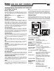
FAN COIL UNIT CONTROLS 1.00 0.80 AC INDUCTION 0.60 0.40 0.20 NAILOR EPIC 0.00 0 100 200 300 CFM 400 500 600 700 Comparison at 800 CFM for model series 39 0.80 0.70 The following graphs show the energy savings of units with EPIC Fan Technology® compared to units with PSC motors. The Engineered Comfort airflows are shown at relatively lower set points (81%) due to a lower discharge air temperature (See control sequence for further explanation). 0.
FAN COIL UNIT CONTROLS Variable Air Volume EPIC Fan Technology® Fan Coil Operation with Constant Discharge Air Temperature THE SOLUTION The attached sequence of operation (See Figure 2) and psychometric chart (Figure 3), illustrate how the EPIC control sequence utilizes variable air volume control, chilled water valve modulation and constant discharge air temperature to control a typical space using our unique controls.
FAN COIL UNIT CONTROLS ΔT1 = 74 – 55 = 19 ΔT2 = 76 – 52 = 24 CFM2 = CFM1 x 0.79(19 ) 24 Example 2: ΔT1 = 78 – 55 = 23 ΔT2 = 79 – 52 = 27 23 CFM2 = CFM1 x 0.85( ) 27 Average = 0.79 + 0.85 = 0.82 2 Average CFM2 = CFM1 x 0.82 (0.72 + 0.85) 2 Std. FCU (CFM1) = 300 400 600 800 1000 1200 EPIC FCU (CFM2) = 246 328 492 656 820 984 Table 1.
FAN COIL UNIT CONTROLS Analog Electronic Controls Variable Air Volume • EPIC Fan Technology® • ECM Motor FEATURES: • Proportional + Integral control action provides precise flow and temperature control. • Standalone operation. • Pressure Independent fan operation ensures airflow settings remain constant. • Factory calibrated controls simplify field installation and eliminate field balancing. • Less costly than digital controls with no software programming requirement.
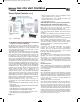
FAN COIL UNIT CONTROLS Analog Control Thermostat and Controller LCD Analog Thermostat MODEL: CTE-5201W36 The CTE-5201W36 single output with limits and PI function thermostat is designed to be used with the CEE-5201 Fan Coil Unit controller. The thermostat comes with the following factory default settings: Set Point (Default): 70°F (21.1ºC) F/C Mode: Degrees F MAX: 100% MIN: 20% PROP: 4ºF (2.
FAN COIL UNIT CONTROLS Analog Fan Coil Unit Controller MODEL: CEE-5201 The Engineered Comfort CEE-5201 controller is mounted inside the controls enclosure on the fan coil unit and is factory wired. Engineered Comfort fan coil units with analog controls provide extremely accurate variable air volume control. They are factory calibrated for each unit permitting quick and easy start-up with no field settings required, but may be simply and easily field adjusted if necessary to suit changing requirements.
FanCoilUnits-New_FanCoilUnits 9/29/14 9:06 AM Page D9 FAN COIL UNIT CONTROLS Direct Digital Controls ® EZstat – The All-In-One Fan Coil Digital Controller Control Options: • Variable Air Volume (VAV) EPIC Fan Technology® with ECM • 3-Speed ECM • 3-Speed PSC 1.
FanCoilUnits-New_FanCoilUnits 9/29/14 9:06 AM Page D10 FAN COIL UNIT CONTROLS Direct Digital Controls (con’t) Comunication with other BACnet network devices and remote monitoring BMS integrated temperature sensing • Water temperature sensor • Discharge air temperature • Remote space temperature Three inputs for external sensors Readily supports Engineered Comfort control sequences Quick (temporary network access through computer 24 Volts data port AC power requires a convertor Fig.
FanCoilUnits-New_FanCoilUnits 9/29/14 9:06 AM Page D11 FAN COIL UNIT CONTROLS Direct Digital Controls (con’t) The following are examples of two Engineered Comfort control sequences: 52 °F DISCHARGE TEMP. RF E AT TW MIN. DEAD BAND W LO 20 Design Indoor use only Weight Approx. 6 oz. (170 grams) 24 VAC (-15%, +20%), 50 – 60 Hz, 12 VA, Supply Voltage non supervised (all circuits, including supply voltage, are power limited circuits) 2°F -2 °F HEATING SETPOINT COOLING SETPOINT Fig.
FAN COIL UNIT PIPING PACKAGES GENERAL NOTES: Basic System Types and Application: 1.
FAN COIL UNIT PIPING PACKAGES Model Series: 39VH and 39L Vertical Hi-Rise Units • 2-Way Valves 2-Way Chilled / Hot Water Valve Basic Package Code 2-Position Actuator 202 203 210 211 212 213 214 Modulating Actuator 402 403 410 411 412 413 414 Options Components BV BVPT FC FCC Options Package Code 01 02 03 04 05 AFS • • • • • • • • • • • Components YS YSB PTO • • • • • • • Legend: • Notes: 1. Select a Basic Package for each valve and an Options Package if required. 2.
FAN COIL UNIT PIPING PACKAGES Model Series: 39VH and 39L Vertical Hi-Rise Units • 3-Way Valves 3-Way Chilled / Hot Water Valve Basic Package Code 2-Position Actuator 302 303 310 311 312 313 314 Modulating Actuator 502 503 510 511 512 513 514 Options Components BV BVPT FC FCC Options Package Code 01 02 03 04 05 06 07 08 09 10 AFS • • • • • • • • • • • • Notes: 1. Select a Basic Package for each valve and an Options Package if required. 2.
FAN COIL UNIT PIPING PACKAGES Model Series: 35F and 37F Horizontal Fan Coil Units • 2-Way Valves 2-Way Chilled / Hot Water Valve Basic Package Code 2-Position Actuator 201 202 203 204 205 206 210 211 212 213 214 Modulating Actuator 401 402 403 404 405 406 410 411 412 413 414 Options Components BV BVPT FC FCC Options Package Code 01 02 03 04 05 AFS • • • • Components YS YSB PTO • • • • • • • • • • • • • • Legend: • • • • Notes: 1.
FAN COIL UNIT PIPING PACKAGES Model Series: 35F and 37F Horizontal Fan Coil Units • 3-Way Valves 3-Way Chilled / Hot Water Valve Basic Package Code 2-Position Actuator 301 302 303 304 305 306 310 311 312 313 314 Modulating Actuator 501 502 503 504 505 506 510 511 512 513 514 Options Components BV BVPT FC FCC Options Package Code 01 02 03 04 05 06 07 08 09 10 AFS • • • • • • • • • • • • • • • Components YS YSB PTO BPV • • • • • • • • • • • • • • • • • • Legend: Notes: BV Ball Valve
FAN COIL UNIT PIPING PACKAGES Components and Specifications Engineered Comfort Vertical Hi-Rise fan coil units are supplied as standard with a factory supplied and installed valve package for the main cooling coil and optional heating coil. This assures all components are compatible with the application and install with the physical restrictions of the cabinet for ease of maintainance and service.
FAN COIL UNIT PIPING PACKAGES 2-Way Modulating Valve / Actuator Control 3-Way Modulating Control Valve / Actuator Valve operation is described above. Actuators use a 0 – 10 Vdc control signal, are fail-inplace design (non-spring return) and provide proportional control from minimum to maximum water flow through the coil in response to room demand from a compatible controller. Modulating valves are standard on Nailor analog and digital EPIC control package chilled water valves.
FAN COIL UNIT PIPING PACKAGES Y Strainer (YS) An inline fitting designed to allow water to flow through a built in removable screen to filter debris or contaminates. With the water system isolated, the plug can be removed from the blowdown leg and the captured debris removed from the screen. Nominal size: 1/2" or 3/4" Pressure rating: 600 psig max. Body: Forged brass Temperature rating: 325ºF max. Screen: 20 mesh, 304 stainless steel Cv: 5.5 (1/2"), 9.
FAN COIL UNITS Electric Heating Coils • Application Guidelines When considering the capacity and airflow for the heater, discharge air temperature can be an important factor. Rooms use different types of diffusers, and they are intended to perform different functions. Slots that blend the air at the glass and set up air curtains within the room, must be able to blow the air very low in the room. Hot air will be too buoyant to be effective in this case.